
Vehicle and chain play adjusting device thereof

A vehicle and chain technology, applied in the field of layout structure of the buffer unit, can solve the problems such as the reduction of the supporting rigidity of the rear hub 12, achieve the effects of reducing weight, reducing length, and preventing malicious damage

Inactive Publication Date: 2005-10-05
HONDA MOTOR CO LTD
View PDF7 Cites 0 Cited by
  • Summary
  • Abstract
  • Description
  • Claims
  • Application Information

AI Technical Summary

Problems solved by technology

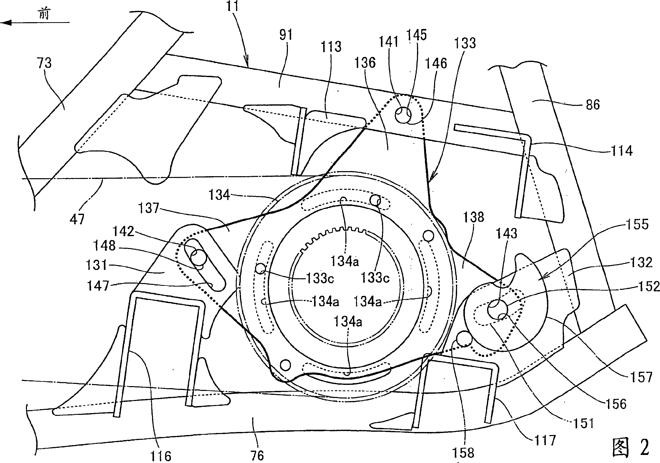
[0015] Since the rear hub 12 has such a structure that it is to be elongated in the front-rear direction by being mounted on the elongated holes 10a, 10b formed on the support plates 7a, 7b by the bolts 23, 23, the The load acting on the rear hub 12 in the front-rear direction of the vehicle reduces the supporting rigidity of the rear hub 12, and in addition, when adjusting the gap of the chain, many troubles are caused

Method used


Image

  • Vehicle and chain play adjusting device thereof
  • Vehicle and chain play adjusting device thereof
  • Vehicle and chain play adjusting device thereof

Examples


Embodiment Construction

[0092] A preferred embodiment of the present invention will be described below with reference to the accompanying drawings. These figures are to be viewed in the direction in which the reference numerals are viewed in the correct manner.

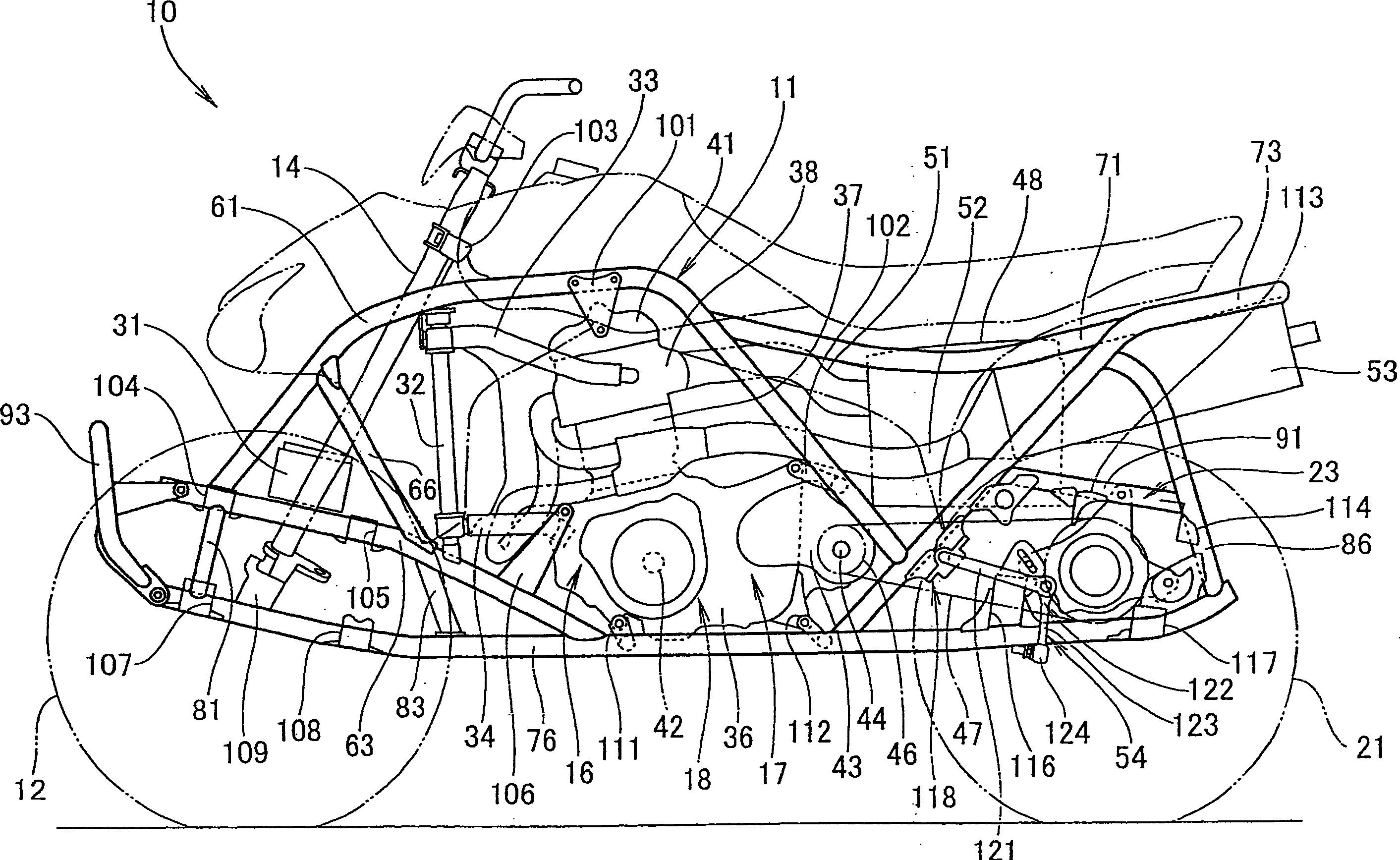
[0093] figure 1 is a side view of the rough-terrain vehicle according to the present embodiment. The rough-terrain vehicle 10 is a vehicle that includes a steering shaft 14 for turning left and right front wheels 12, 13 (reference numeral 12 is shown only on the near side in the figure), and these front wheels are mounted At the front portion of the vehicle body frame 11; a power unit 18, which includes an engine 16 and a transmission box 17 installed in the middle of the vehicle body frame 11; a driving force transmission unit 23, which is used to transmit driving force to the left and right rear wheels 21, 22 ( In the figure, only the reference numeral 21 is marked on the near side, and these rear wheels are mounted on the rear portion ...


PUM


Abstract

An irregular ground travel vehicle is a vehicle where rear wheels as right and left wheels are independently suspended via right and left lower arms, and an anti-roll bar device is suspended between the right and left lower arms. The right and left rear wheels are driven from an engine side via the chain, and the anti-roll bar device is arranged so as to cross the inside of the ring of the chain.

Description

[0001] This application claims the benefits of Japanese patent application Nos. JP 2004-101323 (filed on March 30, 2004), JP 2004-101350 (filed on March 30, 2004) and JP 2004-101362 (filed on March 30, 2004) Foreign Priority to Patent Applications, the contents of which are incorporated herein by reference. technical field [0002] The present invention relates to a vehicle, and more particularly to an arrangement structure of a connecting element for connecting a left suspension arm and a right suspension arm, a chain gap adjusting device, and a buffer unit of the vehicle. Background technique [0003] In the prior art, a stabilizer is known as a connecting element extending between the left and right lower arms for supporting the left and right wheels (for example, see JP-A-2001-328410 ). [0004] The following will describe in JP-A-2001-328410 Figure 1 to Figure 3 . The reference numerals used here refer to those in JP-A-2001-238410. [0005] The stabilizer 29 is conn...

Claims


Application Information

Patent Timeline
IPC IPC(8): A63B22/12B60G3/24B60G7/00B60G21/05B60G21/055B60K17/04B62K5/00B62K11/00B62K25/04B62M9/16F16H57/02
CPCB60G2202/135B60G2200/422B60G2204/1224B60G21/0551B60G3/24B62K5/01B60G2200/141B62K2005/001
Inventor 关文三稻见重人
Owner HONDA MOTOR CO LTD
Learn More