
Tracking system and method

A tracking system and tracking error technology, applied in the field of tracking systems, can solve problems such as failure of radial displacement tracking

Inactive Publication Date: 2005-09-28
KONINKLIJKE PHILIPS NV
View PDF0 Cites 2 Cited by
  • Summary
  • Abstract
  • Description
  • Claims
  • Application Information

AI Technical Summary

Problems solved by technology

In other words, the described method results in a failure to track the radial displacement

Method used


Image

  • Tracking system and method
  • Tracking system and method
  • Tracking system and method

Examples


Embodiment Construction

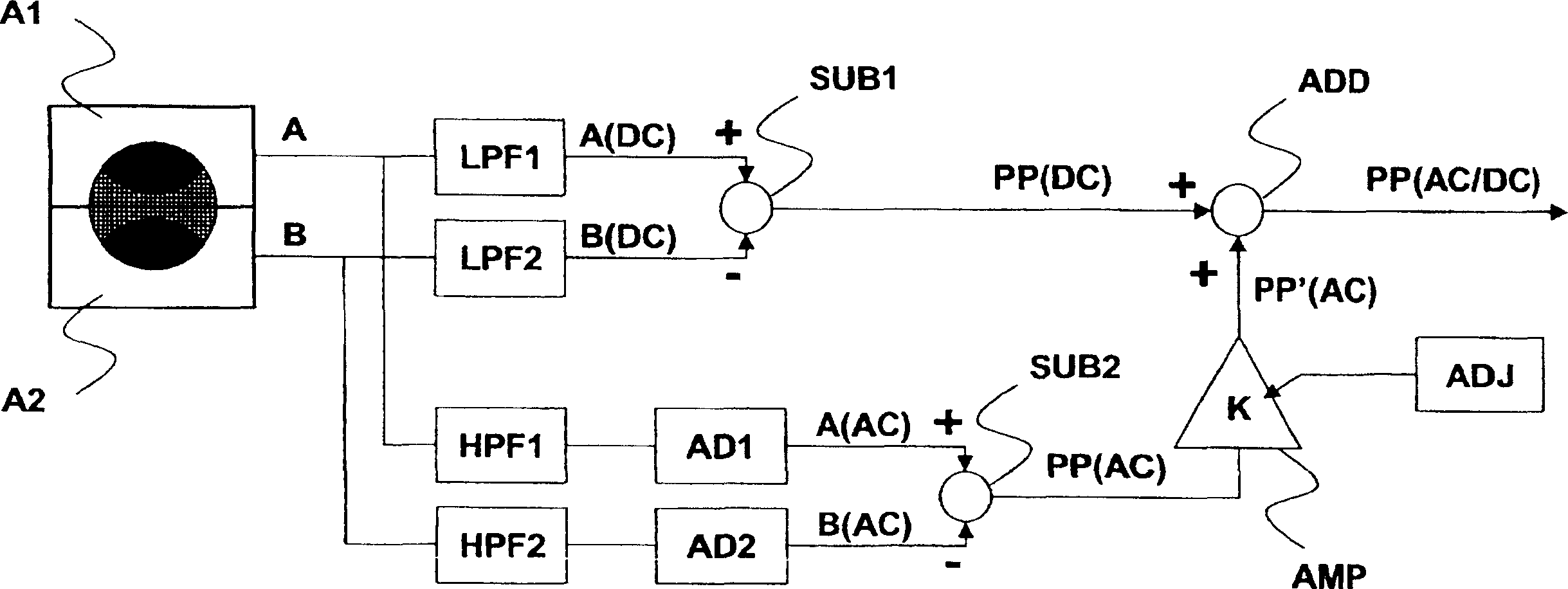
[0029] figure 2 A tracking system for generating a radial tracking error signal according to the invention is described.

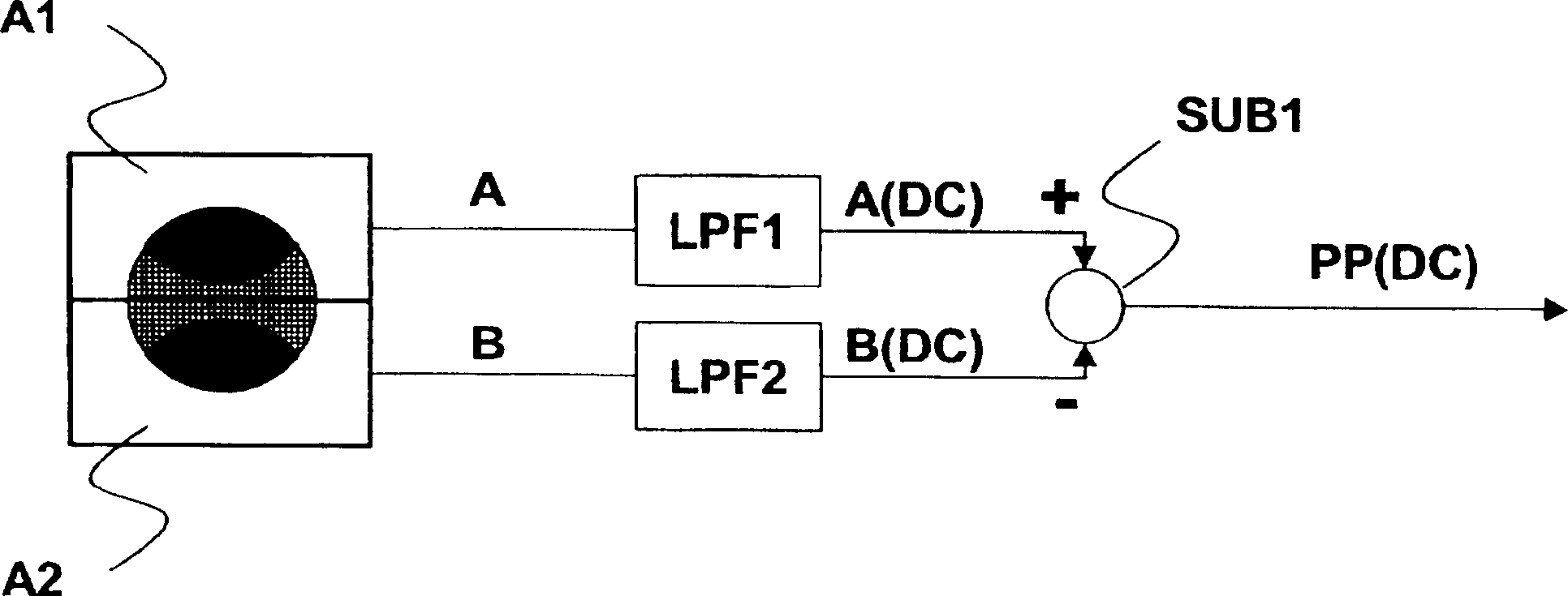
[0030] The tracking system comprises a photodetector comprising two areas A1 and A2 for detecting the reflected light beam of the light spot. The photodetector produces two output signals A and B.

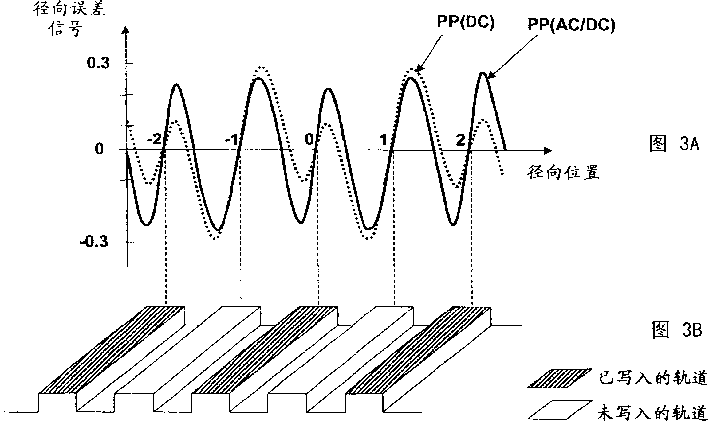
[0031] The invention uses the high frequency content of the output signals A and B in order to generate the improved tracking error signal PP(AC / DC). The high-frequency components are caused by short marks present on the disc, which have different reflectivity factors based on the recorded digital data. High frequency components exist in written tracks / areas, but not in unwritten tracks / areas.

[0032] For the writing track, the amplitude signals A(AC) and B(AC) of the high-frequency signals of the two detector halves produce sinusoidal changes with the change of the track position, and are used to generate the DC push-pull signal PP(DC) The low frequency ...


PUM


Abstract

Tracking system for guiding an optical beam on tracks on an optical disc, said tracking system comprising a photodetector (A1, A2) for detecting optical beams derived from said optical beam, said photodetector generating a first output signal (A) and a second output signal (B), said tracking system comprising first processing means for generating a first differential signal (PP(DC)) corresponding to the low-frequency part of a difference between said first and second output signals. The tracking system comprises second processing means for generating a tracking error signal (PP(AC / DC)) defined by the addition of said first differential signal (PP(DC)) to a second differential signal (PP'(AC)), said second differential signal corresponding to a fraction of the difference in amplitude of the high-frequency components of said first and second output signals. Use: Optical disc player / writer.

Description

technical field [0001] The invention relates to a tracking system for guiding a light beam on a track of an optical disc, said tracking system comprising a photodetector for detecting a light beam derived from said light beam, said photodetector producing a first output signal and a second For two output signals, the tracking system includes first processing means for generating a first differential signal corresponding to the low frequency portion of the difference between the first and second output signals. [0002] The invention can be used in the field of optical recording. Background technique [0003] A method of maintaining a light spot on a track of an optical disc is known as a DC push-pull method. The method involves generating a tracking error signal known as a push-pull signal. The tracking error signal results from the interaction of the light spot with grooves or other tracking structures located on the surface of the disc and corresponds to a default error ...

Claims


Application Information

Patent Timeline
Patent Type & Authority Applications(China)
IPC IPC(8): G11B7/085G11B7/09G11B7/095
CPCG11B7/094G11B7/0901G11B7/095G11B7/08517G11B7/085G11B7/09
Inventor S·斯塔林加M·凯珀A·斯特克
Owner KONINKLIJKE PHILIPS NV
Learn More