


Quick Research
Generate reliable direction feasibility study reports for your R&D in just a few steps.

Technical Q&A
Discover and master advanced knowledge NOW. Basics, ideas, possibilities, all at once.

Find Solutions
As an expert in R&D theories, this can generate solutions to your technical problems instantly.

Evaluate Feasibility
Analyze your overall solution with one click, know your potential R&D risks in advance.

Monitor Landscape
Get weekly tech updates, stay abreast of the latest tech innovations and key insights.
Pneumatic tire
一种充气轮胎、轮胎的技术,应用在轮胎零部件、胎沿、车轮等方向,能够解决驾驶舒适度变差、垂直刚度常数上升等问题,达到不降低驾驶舒适度、提高操控稳定性的效果
- Summary
- Abstract
- Description
- Claims
- Application Information
AI Technical Summary
Problems solved by technology
Method used
Image

Examples
Embodiment
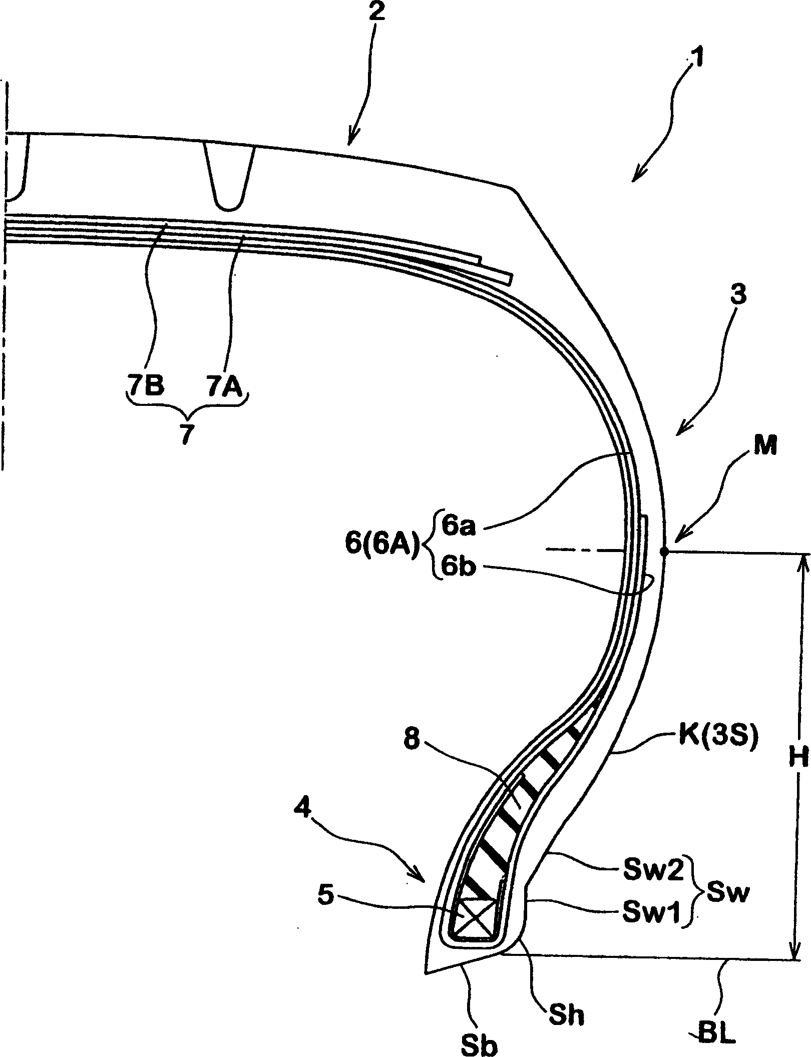
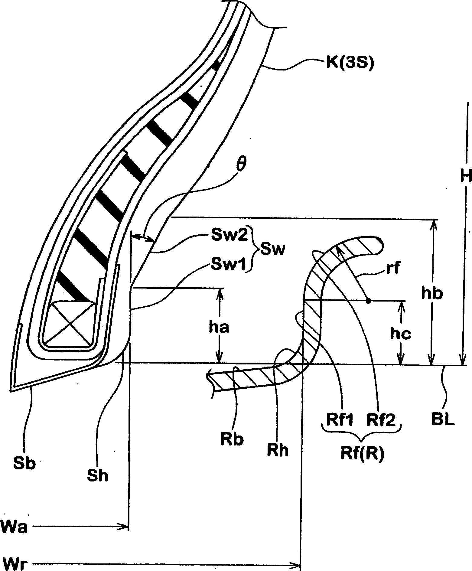
[0042] Based on the specifications shown in Table 1, will have as figure 1 A passenger car tire with the structure shown and the tire size of 215 / 40R17 was used as a sample. The handling stability and driving comfort of the sample tires were tested and compared with each other. The specifications are the same except as shown in Table 1. The rim used here is a standard rim (17×7.5JJ) in the JATMA standard, the height hc of the vertical surface portion Rf1 in the rim surface Rf is 9.0 mm, and the curvature radius of the curved surface portion Rf2 is 9.0 mm.
[0043] (1) Handling stability and driving comfort
[0044] The sample tires were fitted to four wheels of a car (2000cc, FR car) having a rim (17×7.5JJ) with an internal pressure of 230 kPa, and the car was run on an ordinary road and a circular track with a dry asphalt surface. Rely on the sensory evaluation of the driver, define 6 as a benchmark with the numerical value of the traditional embodiment, and control stabi...
PUM
 Abstract
Description
Claims
Application Information
 - R&D Engineer
- R&D Manager
- IP Professional
- Industry Leading Data Capabilities
- Powerful AI technology
- Patent DNA Extraction
Browse by: Latest US Patents, China's latest patents, Technical Efficacy Thesaurus, Application Domain, Technology Topic, Popular Technical Reports.
© 2024 PatSnap. All rights reserved.Legal|Privacy policy|Modern Slavery Act Transparency Statement|Sitemap|About US| Contact US: help@patsnap.com