
Engine fuel injection device and engine fuel injection method

A fuel injection device and fuel injection technology, which are applied in the directions of fuel injection device, fuel injection control, engine components, etc., can solve the problems of deterioration of emission performance, reduction of engine torque, hysteresis, etc.

Inactive Publication Date: 2005-09-07
TOYOTA JIDOSHA KK
View PDF1 Cites 14 Cited by
  • Summary
  • Abstract
  • Description
  • Claims
  • Application Information

AI Technical Summary

Problems solved by technology

However, this can cause a lag in fuel pressurization when the engine operation is switched from idle to, for example, a high load condition
In this case, the fuel will be under-pressurized, or not to the level required for a high-load engine operation
[0005] As mentioned above, if the actual fuel pressure cannot achieve the desired level, the fuel injected by the direct injector will not be sufficiently atomized
This hinders the combustion of fuel in an unfavorable manner, reduces engine torque, and worsens emissions performance

Method used


Image

  • Engine fuel injection device and engine fuel injection method
  • Engine fuel injection device and engine fuel injection method
  • Engine fuel injection device and engine fuel injection method

Examples


Embodiment Construction

[0017] A fuel injection device according to an embodiment of the present invention will be described below.

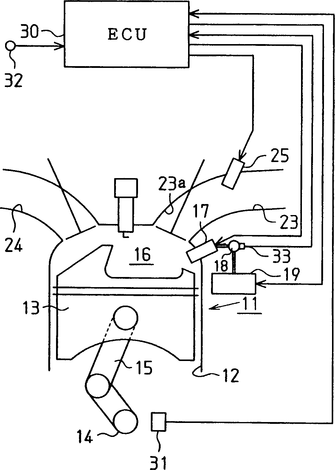
[0018] refer to figure 1 , the fuel injection device is applied to an internal combustion engine 11 mounted on a vehicle. The engine 11 has a piston 13 which is located in a cylinder 12 . Piston 13 is connected to crankshaft 14 via a connecting rod 15 , which converts the reciprocating motion of piston 13 into rotational motion of crankshaft 14 .

[0019] Combustion chamber 16 is defined as the space above piston 13 in cylinder 12 . A direct injector 17 is located within the combustion chamber 16 for injecting fuel directly into the combustion chamber 16 . The direct injector 17 is connected to a fuel pressurization system, the structure of which is described below. That is, a delivery pipe 18 is connected to the direct injector 17 . A feed pump 19 is connected to the transfer pipe 18 and pressurizes fuel from a fuel tank (not shown) to a relatively high level. F...


PUM


Abstract

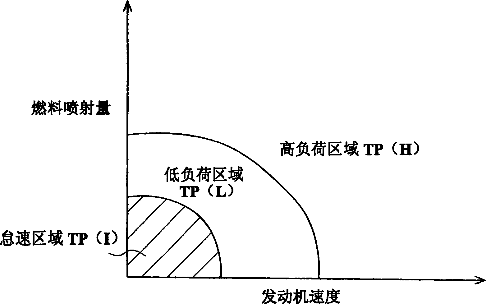
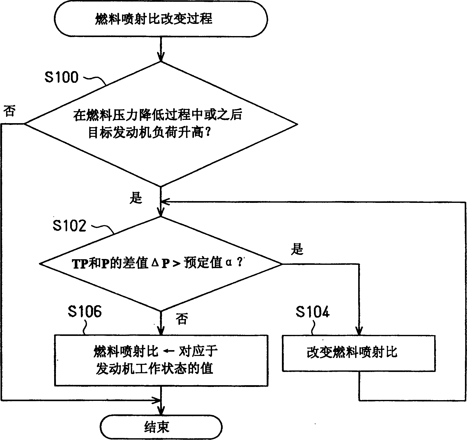
A fuel injection device for an engine includes a direct injector and an intake passage injector. When the engine load is relatively low, a fuel pressure lowering procedure is executed for lowering the pressure of fuel supplied to the direct injector. An ECU sets a fuel injection ratio, which is the ratio between the fuel injection amount of the direct injector and that of the intake passage injector, based on the engine operation state. The ECU changes the fuel injection ratio such that the ratio of the fuel injection amount of the direct injector to the total amount of the fuel fed to a combustion chamber is decreased, until the pressure of the fuel supplied to the direct injector is raised from the value lowered through the fuel pressure lowering procedure to a predetermined permissible value. This effectively suppresses hampering of the engine combustion, caused by the lowered fuel pressure.

Description

technical field [0001] The present invention relates to a fuel injection device and fuel injection method suitable for an internal combustion engine having a direct injector directly injecting fuel into a combustion chamber and a port injector injecting fuel into an intake port. Background technique [0002] Conventionally, as described in Japanese Laid-Open Patent Publication No. 2002-364409, there is a common fuel injection device capable of switching fuel injection modes. More particularly, the fuel injection device is used in an internal combustion engine having a direct injector injecting fuel directly into a combustion chamber and a port injector injecting fuel into an intake port. The fuel injector switches the fuel injection mode by selecting the operation of the direct injector or the port injector. [0003] Since the pressure inside the combustion chamber is relatively high, the fuel injection pressure (fuel pressure) of the direct injector injecting fuel into the...

Claims


Application Information

Patent Timeline
Patent Type & Authority Applications(China)
IPC IPC(8): F02M63/00F02B3/00F02B7/00F02B17/00F02D29/00F02D41/02F02D41/04F02D41/34F02D41/38F02D41/40F02D45/00
CPCF02D2250/31F02D41/40Y02T10/44F02D41/3836F02D41/3094Y02T10/40
Inventor 大谷元希
Owner TOYOTA JIDOSHA KK
Learn More