Device for manufacturing mechanical shaft in operation

A technology of processing equipment and machinery, applied in the field of accompanying mechanical processing equipment, can solve problems such as time-consuming and labor-intensive, and achieve the effect of simple structure, shortening repair cycle and cost, and convenient transportation with vehicles

Inactive Publication Date: 2005-08-31
SHENYANG DALU LASER TECH
View PDF0 Cites 2 Cited by
  • Summary
  • Abstract
  • Description
  • Claims
  • Application Information

AI Technical Summary

Problems solved by technology

Generally, the repair work of the rotor shaft needs to remove the rotor shaft from the steam turbine or generator, and transport it to the machining factory, which is troublesome and time-consuming

Method used


Image

  • Device for manufacturing mechanical shaft in operation

Examples


Embodiment

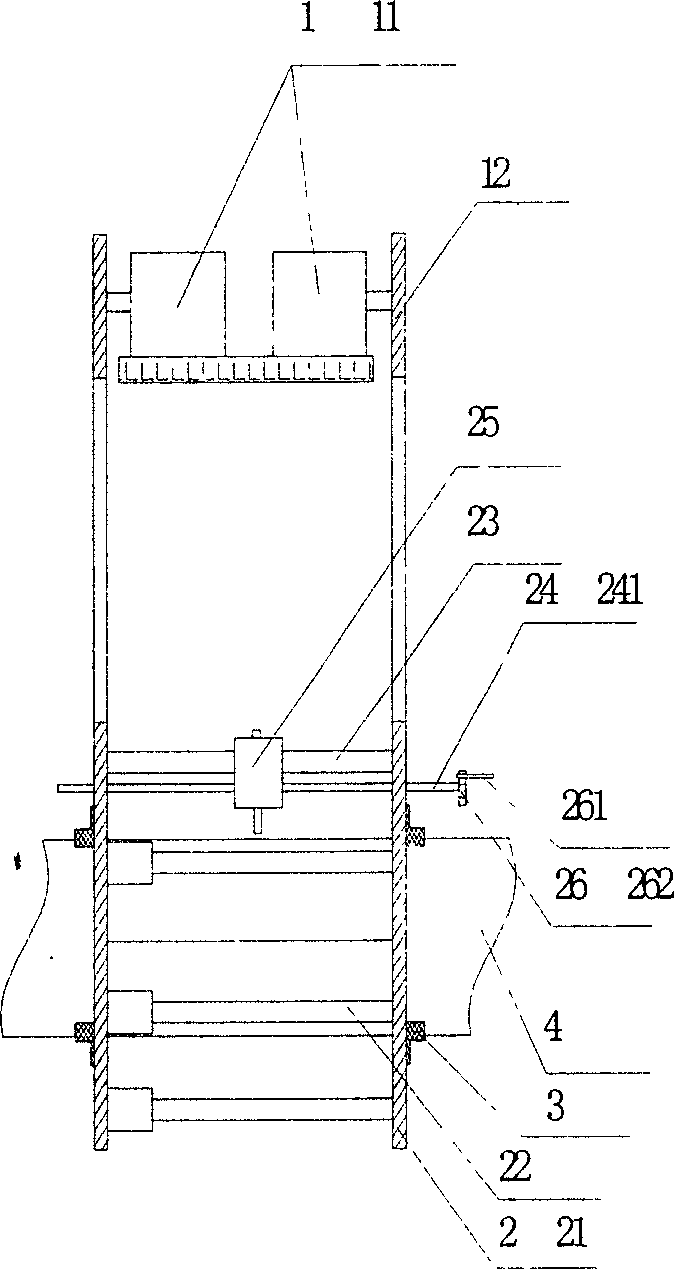
[0024] Example traveling mill

[0025] The traveling mill is composed of a driving mechanism (1), a rim tool rest assembly (2), a chuck (3) and a cutting tool.

[0026] The driving mechanism (1) is composed of a frequency-variable speed-regulating motor (11) and a transmission mechanism (12), and the molded product is selected according to the calculated motor power and corresponding rotating speed. For making transmission stable, adopt two shaft extension reducers, drive sprocket is installed on its two ends shaft head, and passive sprocket is exactly the rim (21) of rim knife rest assembly (2). The transmission mode of drive mechanism (11) and wheel rim knife rest assembly (2) selects chain drive, and purpose makes adjusting flexibly, is applicable to the condition and the environment of on-the-spot changeable.

[0027] Wheel rim knife rest assembly (2) is made up of wheel rim (21), adjustable connecting rod (22), guide rail, (23), knife rest (25). Wheel rim (21) is the co...


PUM


Abstract

A follow-up machining apparatus for greater mechanical axle (workpiece) is composed of a locating mechanism using said great mechanical axle as reference, a ring-type tool carriage assemblage fixed to said locating mechanism and revolving around said axle, and a driver unit. After said follow-up machining apparatus is fixed to said great axle, the axis is machined by the cutting tool moving around it.

Description

Technical field: [0001] The invention relates to accompanying machining equipment, especially the accompanying machining equipment of a large mechanical shaft. Background technique: [0002] The rotor shafts of steam turbines and generators are large in size and weight, high in precision, complex in manufacturing process, high in production cost and long in cycle. And once there is a problem in operation, its impact is huge. Therefore, the design of this type of rotor is an infinite life design, that is, it can be used continuously for more than 20 years under normal working conditions. [0003] The general manufacturing process of the rotor shaft includes whole forging type, sleeve type, combined type and welding type. Regardless of the structural form, its quality requirements are relatively high. Due to working at high temperature and high speed, the material is required to have a high creep limit, good durable strength and good thermal fatigue and fracture resistance....

Claims


Application Information

Patent Timeline
Patent Type & Authority Applications(China)
IPC IPC(8): B23P23/02
Inventor 陈江王德富王一兵张静波
Owner SHENYANG DALU LASER TECH
Why Eureka
Try Eureka