Compressor protective method and structure

A technology for protecting structures and compressors, applied in compressors, irreversible cycle compressors, refrigerators, etc., can solve problems such as lower production performance, lower performance, and higher costs, to prevent cost increases and prevent the number of parts. the added effect of

Inactive Publication Date: 2005-08-24
SANDEN CORP
View PDF2 Cites 1 Cited by
  • Summary
  • Abstract
  • Description
  • Claims
  • Application Information

AI Technical Summary

Problems solved by technology

[0005] However, since the method of installing a heater such as a band heater on the compressor requires the installation of a dedicated heater, it is inevitable that the production performance will be reduced or the cost will be increased.
[0006] On the other hand, since the method of providing a safety passage with a safety valve will complicate the structure, there is also a problem that the production performance is reduced or the cost is increased, thereby causing a performance reduction.
Moreover, this method also has the problem that the decompression effect in the compressor cannot be sufficiently obtained.
There is also the problem that it cannot be easily applied to existing compressors

Method used


Image

  • Compressor protective method and structure
  • Compressor protective method and structure
  • Compressor protective method and structure

Examples


Embodiment Construction

[0017] Next, preferred embodiments of the present invention will be described with reference to the drawings.

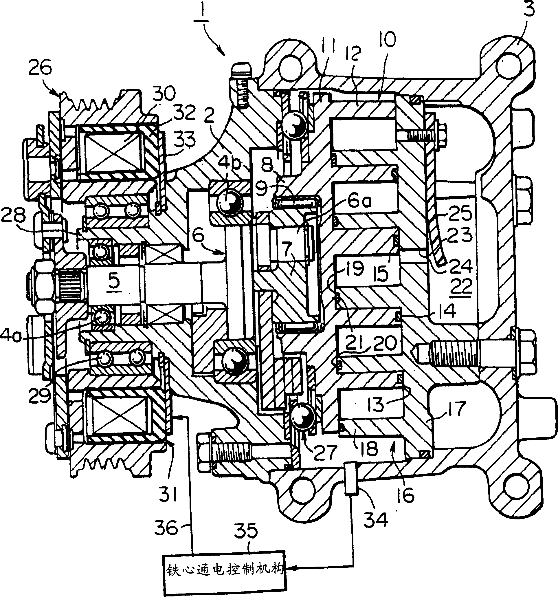
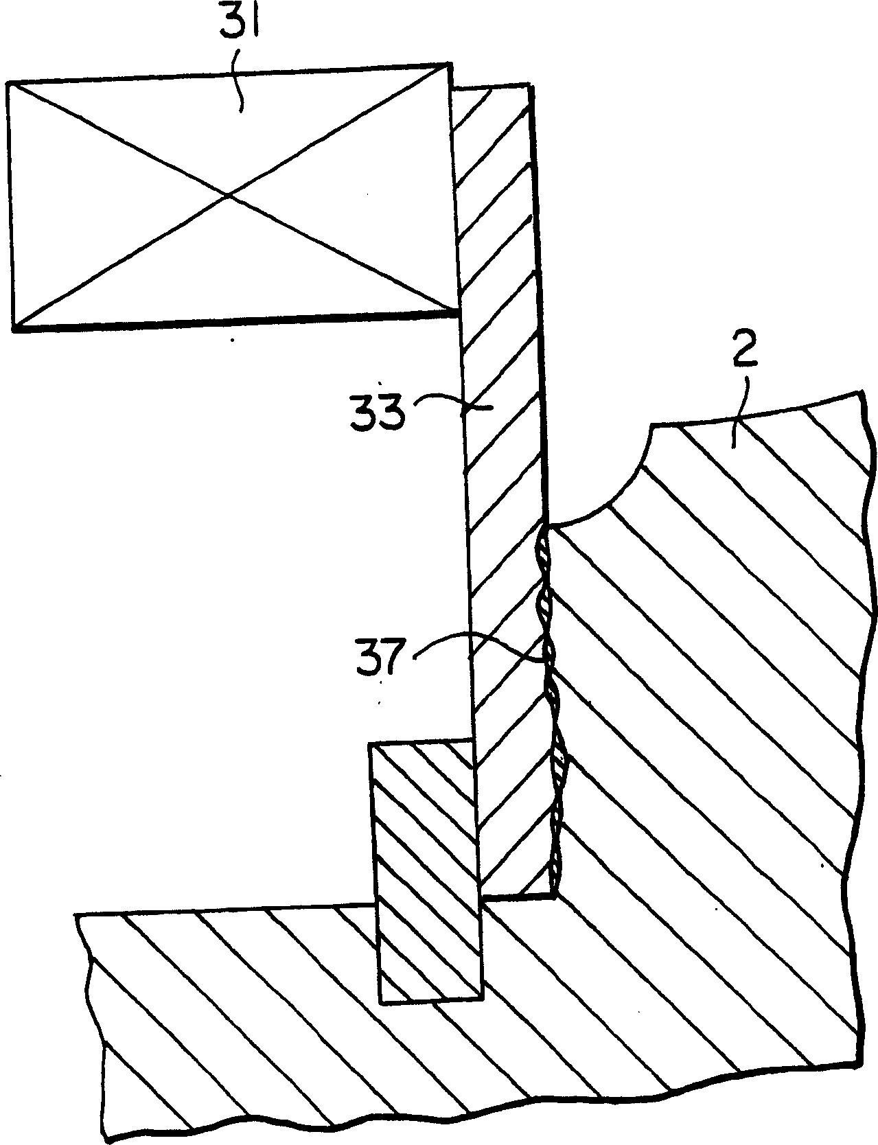
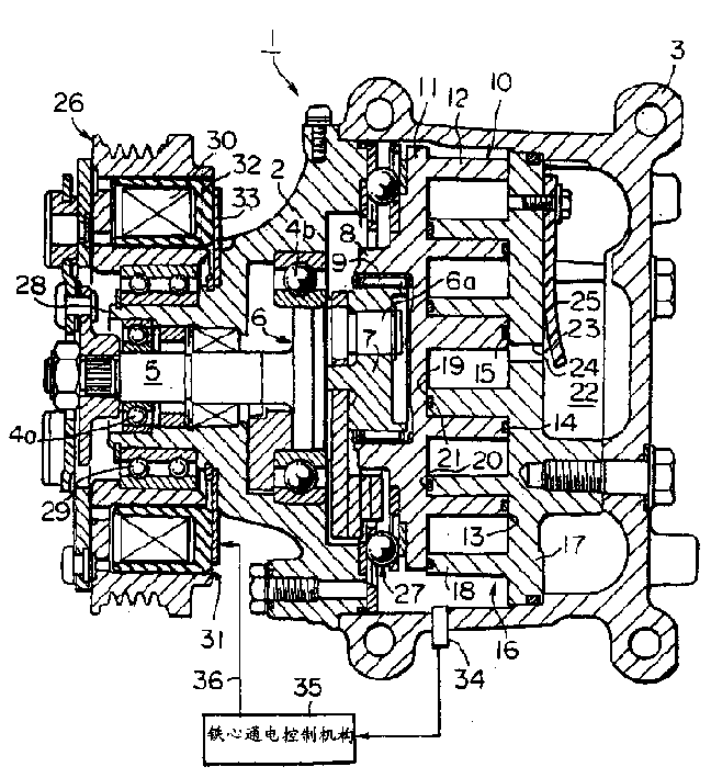
[0018] figure 1 The protection structure of the compressor which concerns on one Embodiment of this invention is shown. figure 1 Middle and 1 represent a scroll compressor, and the compressor 1 has a front casing 2 and a casing 3 .

[0019] The drive shaft 5 is rotatably inserted into the front cabinet 2 via bearings 4a, 4b. A crank mechanism 6 is arranged on one side front end of the drive shaft 5, and the crank pin 6a of the crank mechanism 6 is inserted in an eccentric bush 7, which is arranged at a position deviated from the center of rotation (axis center) of the drive shaft 5. in an eccentric position. The eccentric bushing 7 is freely rotatably inserted in the inner ring of a transmission bearing 9 which is pressed into the annular protrusion 8 of the movable scroll 10 . Between the front casing 2 and the movable scroll 10, a ball coupling 27 for preventin...


PUM


Abstract

A method and device, for protecting a compressor. When the temperature of a compressor having an electromagnetic clutch is equal to or below a preset predetermined value during the stop of the compressor, electricity is supplied to a core of the electromagnetic clutch so that the core functions as a heater to raise the temperature of the compressor above the predetermined temperature. Protection of the compressor is achieved with a simple structure and low costs because there is no need to provide a dedicated heater for raising the temperature of the compressor.

Description

technical field [0001] The present invention relates to a protection method and a protection structure of a compressor, more specifically, a protection method and a protection structure applicable to a compressor equipped with an electromagnetic clutch in an air conditioner and the like. Background technique [0002] Generally, a compressor having an electromagnetic clutch is installed in a refrigeration circuit of an air conditioner. And after the refrigerant is compressed in the compressor, the refrigerant is sent to the refrigeration circuit system. Although the above-mentioned compressor is operated or stopped by turning on and off the electromagnetic clutch, when the compressor is stopped, some amount of refrigerant remains in the compressor. However, when the compressor is still left in a low-temperature state where the operation is stopped for a long period of time, a large amount of refrigerant will be stored in the compressor (that is, a so-called sleep phenomenon ...

Claims


Application Information

Patent Timeline
IPC IPC(8): F04B39/00B60H1/00B60H1/32F04B35/00F04B49/10F04C18/02F04C28/28F04C29/04
CPCF04C28/28F04C29/04F04B49/10
Inventor 北野教夫
Owner SANDEN CORP
Why Eureka
Try Eureka