Magnetron

A magnetron and anode technology, applied in the field of magnetron, can solve the problems of failure to improve oscillation efficiency and deterioration of oscillation efficiency

Active Publication Date: 2005-08-17
PANASONIC CORP
View PDF1 Cites 3 Cited by
  • Summary
  • Abstract
  • Description
  • Claims
  • Application Information

AI Technical Summary

Problems solved by technology

However, on the other hand, this structure has another problem of deterioration of oscillation efficiency
[0020] Further, in the magnetron described in Patent Document 1, reduction of line noise is achieved, but oscillation efficiency is not improved

Method used


Image

  • Magnetron
  • Magnetron
  • Magnetron

Examples


Embodiment Construction

[0044] Hereinafter, preferred embodiments of a magnetron according to the present invention will be described in detail with reference to the accompanying drawings.

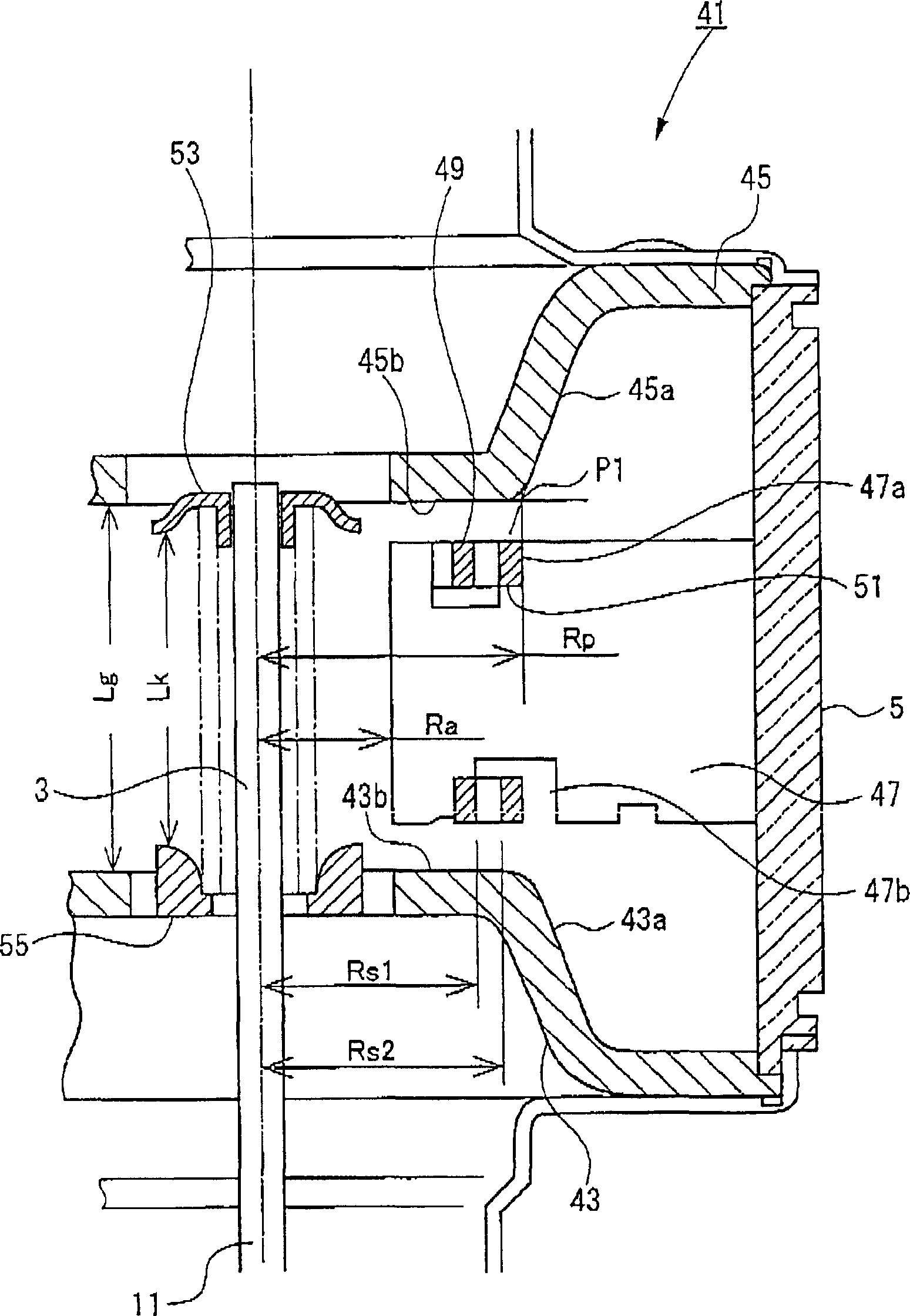
[0045] attached figure 1 is a longitudinal sectional view showing a magnetron according to an embodiment of the present invention.

[0046] According to the embodiment of the present invention, the magnetron 41 and the attached Figure 8 and 9 The conventional magnetron 1 shown has the same structure, except that input pole piece 7 is replaced by input pole piece 41, output pole piece 13 is replaced by output pole piece 45, anode vane 20 is replaced by anode vane 47, and anode vane 20 is replaced by anode vane 47. The pressure ring 49 replaces the small-diameter pressure equalizing ring 22 , and the large-diameter pressure equalizing ring 51 replaces the large-diameter pressure equalizing ring 24 . In this embodiment, the same elements as those of the conventional magnetron have the same reference numerals, an...


PUM


Abstract

In a magnetron 41, when a radius of a flat portion 45b of a pole piece 45 is Rp, a radius of the inner circumference of a large-diameter equalizing ring 51 is Rs2, Rp >= Rs2, a radius of the outer circumference of a small-diameter equalizing ring is Rs1, a radius of a circle inscribed in a leading edge of an anode vane is Ra, and a minimum length between the pole pieces in the axial direction is Lg, the values of Ra, Rs1, Rs2, and Lg are set such that the following Expressions 1 and 2 are established: Expression 1u 1.85Ra <= (Rs1 + Rs2) / 2 <= 1.96Ra, and Expression 2u 2.84Ra <= Lg <= 3.0Ra. =Rs 2 , a radius of the outer circumference of a small-diameter equalizing ring is Rs 1 , a radius of a circle inscribed in a leading edge of an anode vane is Ra, and a minimum length between the pole pieces in the axial direction is Lg, the values of Ra, Rs 1 , Rs 2 , and Lg are set such that the following Expressions 1 and 2 are establis.

Description

technical field [0001] This invention relates to magnetrons for use in radio frequency heating devices such as microwave ovens. Background technique [0002] attached Figure 8 is a longitudinal sectional view of a conventional magnetron incorporated into a microwave oven. attached Figure 9 is an enlarged longitudinal sectional view showing the attached Figure 8 The main part of the magnetron is shown. in the attached Figure 8 and 9 Among them, the magnetron 1 includes a cathode 3 provided vertically along the central axis; an anode cylinder 5 coaxially surrounding the cathode 3; an input pole piece 7 provided at the end of the lower opening of the anode cylinder 5; The cathode end guide rod 31 protruding from the metal tube 9, the first metal tube covers the input pole piece 7; the output pole piece 13, which is provided at the end of the upper opening of the anode cylinder 5; the second pole piece covering the output pole piece 13 a metal tube 15; and a microwave ra...

Claims


Application Information

Patent Timeline
Patent Type & Authority Applications(China)
IPC IPC(8): H01J23/20H01J23/10H01J25/50H01J25/587
CPCH01J23/20H01J23/10H01J25/587H05B6/64
Inventor 吉原正训落合宏齐藤悦扶大栗英树
Owner PANASONIC CORP
Why Eureka
Try Eureka