Projectile for radially deploying sub-projectiles

A technology of sub-projectiles and projectiles, applied in the direction of warheads, ammunition, projectiles, etc.

Inactive Publication Date: 2005-08-10
METAL STORM LTD
View PDF2 Cites 6 Cited by
  • Summary
  • Abstract
  • Description
  • Claims
  • Application Information

AI Technical Summary

Problems solved by technology

However, this fragmentation projectile can only produce a thin, seashell-like pattern of broken shells

Method used


Image

  • Projectile for radially deploying sub-projectiles
  • Projectile for radially deploying sub-projectiles
  • Projectile for radially deploying sub-projectiles

Examples


Embodiment Construction

[0081] Detailed description of the preferred embodiment

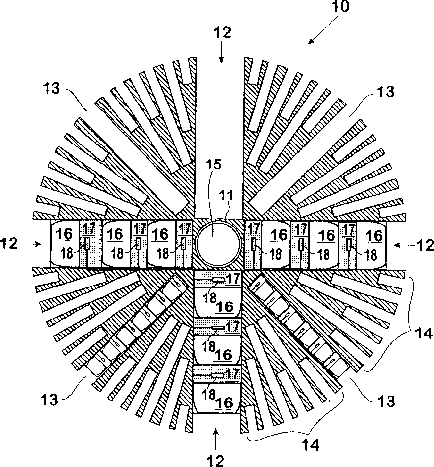
[0082] figure 1 A projectile 10 is shown having six (6) large bore tubes 12 of suitable caliber, but only four (4) large bore tubes 12 are shown in this schematic cross-sectional view. The remaining two (2) large boring tubes (extending perpendicular to the paper) are identified as 11. The cross-sectional schematic also shows four (4) medium bore tubes 13 of medium diameter and forty-eight (48) small bore tubes 14 of smaller bore. As shown, each of the large bore tube 12 , the medium bore tube 13 and the small bore tube 14 includes a plurality of axially disposed sub-projectiles 16 . The sub-projectile 16 is combined with a propellant charge 17 and an ignition device 18 which will then be ignited under the control of an electronic controller 15 . In certain embodiments, the projectile 10 may also include an explosive charge for eventual detonation.

[0083] In such an embodiment, the electronic controller 15 is loca...


PUM


Abstract

A projectile (10) for firing from a barrel, said projectile including a multiplicity of barrel assemblies (12, 13, 14) radially disposed from the centre of mass of the projectile, wherein each of said multiplicity of barrel assemblies includes a plurality of sub-projectiles (16) axially disposed within a barrel; each of said sub-projectiles associated with a discrete propellent charge (17) for propelling a respective sub-projectile from the barrel, wherein said projectile is capable of selectively firing sub-projectiles (16), suitably with the aid of primers (18) each coupled to an electronic controller (15), to provide a predetermined pattern of deployed sub-projectiles. A defence system employing projectiles of the type described is also disclosed, together with a method for disguising the launch location of a projectile utilising divert propulsion.

Description

technical field [0001] The present invention relates to the dispersal of objects having projectile properties, in particular, but not exclusively, to the use of parent projectiles to form a predetermined pattern of dispersal of sub-projectiles, and to a projectile for masking the location at which a projectile is launched launch method. Background of the invention [0002] Projectiles containing explosives have been used as fragmentation devices, which are used to disperse numerous shrapnel fragments. In a simple form, upon detonation of the charge, the casing of such a projectile is fragmented such that the individual casing fragments are radially dispersed to form a shrapnel pattern of approximately spherical surfaces. [0003] In other configurations, the shape of the explosive and the configuration of the casing can be varied to control the fragment pattern. However, this fragmentation projectile can only produce a thinner, seashell-like pattern of broken shells. It w...

Claims


Application Information

Patent Timeline
Patent Type & Authority Applications(China)
IPC IPC(8): F41A19/58F41A19/68F41H11/02F42B12/48F42B12/60F42B12/70F41F1/00
CPCF41A19/68F42B12/60F42B12/70F41A19/58F41H11/02
Inventor 詹姆斯·M·奥德怀尔肖恩·P·奥德怀尔
Owner METAL STORM LTD
Why Eureka
Try Eureka