Ion generator
An ion generating device and electronic technology, which are applied in ion beam tubes, parts of particle separator tubes, food science, etc., can solve the problems of air resistance change, generation of a large amount of ozone, electric shock, etc., and achieve the effect of inhibiting the generation of ozone.
- Summary
- Abstract
- Description
- Claims
- Application Information
AI Technical Summary
Problems solved by technology
Method used
Image
Examples
Embodiment approach 1
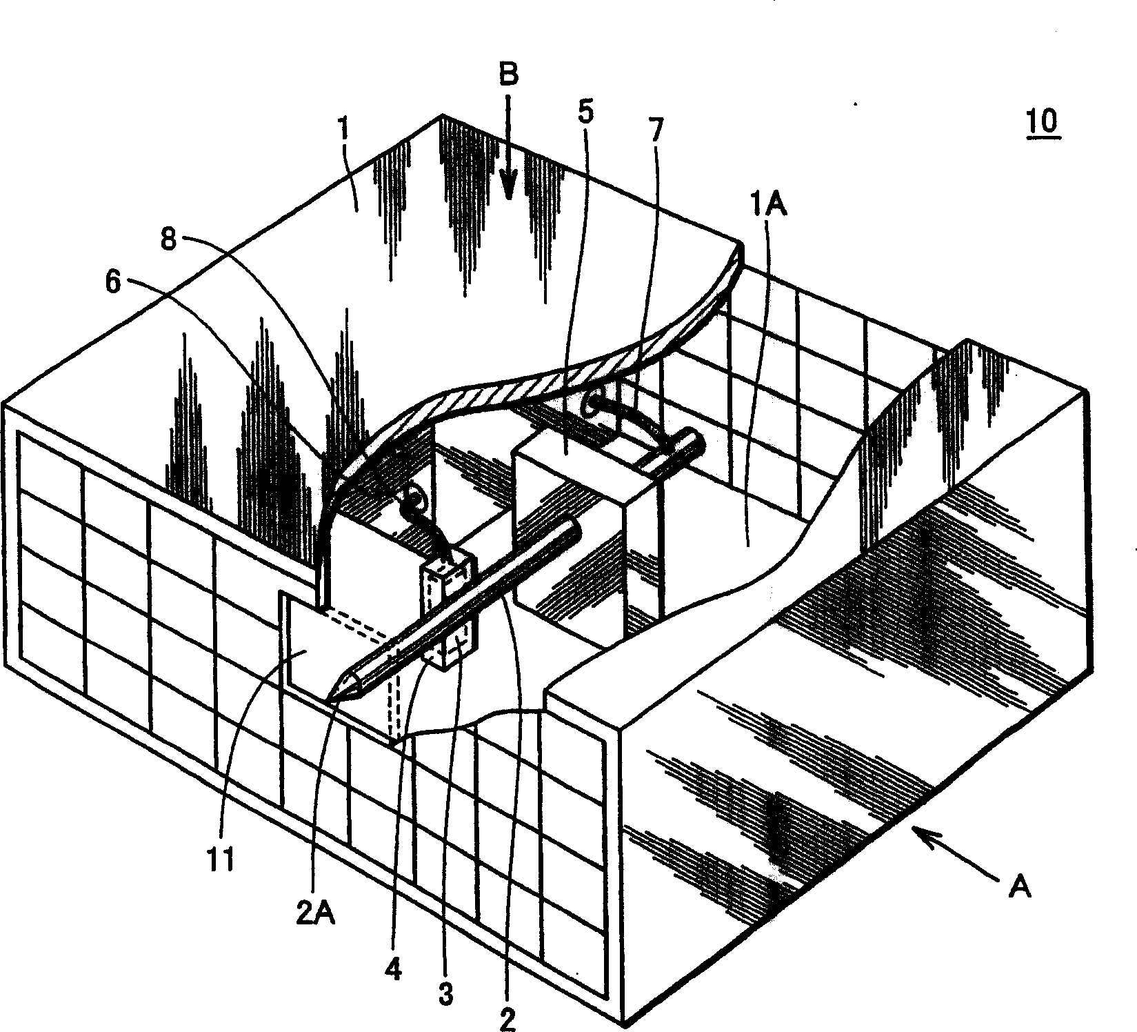
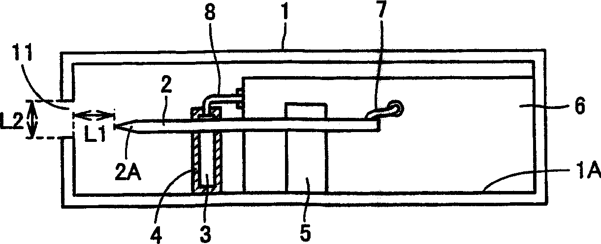
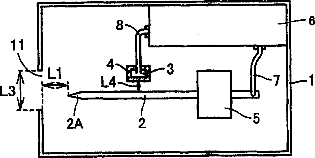
[0084] refer to figure 1 , The negative ion generator 10 of Embodiment 1 has a case 1 , needle electrodes 2 , a counter electrode 3 , an insulator 4 , a support member 5 , a power supply circuit 6 , and wiring 7 , 8 .
[0085] The insulator 4 , the support member 5 and the power circuit 6 are fixed on the bottom surface 1A of the box body 1 . The case 1 has an opening 11 . The needle electrode 2 is made of tungsten with a diameter of 0.5 mm to 1.0 mm. In addition, the needle electrode 2 has a pointed tip 2A, and the tip 2A is fixed to the support member 5 so as to face the opening 11 of the case 1 . Also, the needle electrodes 2 are not covered with an insulator. In addition, the needle electrode 2 is not limited to tungsten, and may be any electrical conductor having a high density and a high heat-resistant temperature.
[0086] The counter electrode 3 is covered with an insulator 4 and arranged at a predetermined distance from the needle electrode 2 . The insulator 4 c...
Embodiment approach 2
[0150] refer to Figure 9 , negative ion generator 10A of Embodiment 2 is a device in which insulator 9 is added and insulator 4 is removed in negative ion generator 10 , and the others are the same as negative ion generator 10 .
[0151] The insulator 9 covers the body part 2C except the front end part 2A and the rear end part 2B of the needle electrode 2 . The body portion 2C of the needle electrode 2 is covered with the insulator 9 to constitute the negative electrode 20 . The negative electrode 20 is fixed to the support member 5 by penetrating the support member 5 with the body portion 2C and the insulator 9 . Rear end 2B of needle electrode 2 is connected to wiring 7 .
[0152] In the negative ion generator 10A, the counter electrode 3 is not covered but the body part 2C of the needle electrode 2 is covered with the insulator 9 . That is, by covering a part of the needle-shaped electrode 2 with the insulator 9 , no current flows between the needle-shaped electrode 2 a...
Embodiment approach 3
[0168] Referring to FIG. 16 , negative ion generator 10B of Embodiment 3 is a device in which insulator 9 is added to negative ion generator 10 , and is the same as negative ion generator 10 in other respects.
[0169] The needle electrode 2 and the insulator 9 constitute a negative electrode 20 . Therefore, the specific material of the insulator 9 , the method of fixing the supporting member 5 to the negative electrode 20 and the method of connecting the negative electrode 20 and the wiring 7 are the same as those described in the second embodiment.
[0170] In negative ion generator 10B, needle electrode 2 and counter electrode 3 are covered with insulators 4 and 9, respectively. Therefore, the counter electrode 3 and the insulator 4 can be arranged at any position in the case 1 as described in the first embodiment.
[0171] In the negative ion generator 10B in which the needle-shaped electrode 2 and the counter electrode 3 are covered by insulators 4 and 9, a negative volt...
PUM
 Abstract
Description
Claims
Application Information
 - Generate Ideas
- Intellectual Property
- Life Sciences
- Materials
- Tech Scout
- Unparalleled Data Quality
- Higher Quality Content
- 60% Fewer Hallucinations
Browse by: Latest US Patents, China's latest patents, Technical Efficacy Thesaurus, Application Domain, Technology Topic, Popular Technical Reports.
© 2025 PatSnap. All rights reserved.Legal|Privacy policy|Modern Slavery Act Transparency Statement|Sitemap|About US| Contact US: help@patsnap.com


