
Projection display device, lighting device and temperature measuring method thereof

A lighting device, temperature measurement technology, applied in thermometers, projection devices, measuring devices, etc., can solve the problems of wire and wire interference cooling flow field, high measurement temperature, temperature overestimation, etc.

Inactive Publication Date: 2005-07-06
BENQ CORP
View PDF1 Cites 0 Cited by
  • Summary
  • Abstract
  • Description
  • Claims
  • Application Information

AI Technical Summary

Problems solved by technology

[0003] At present, in terms of temperature measurement, it is roughly divided into two types: the adhesion of thermal induction detection components (such as thermocouples, thermalcouples) and infrared (IR) measurement. When measuring temperature with thermocouples, it is necessary to measure the adhesion at each key point. If there are too many adhesion measurement points or improper routing, the wires will interfere with the cooling flow field in the lighting device, and the temperature will be overestimated
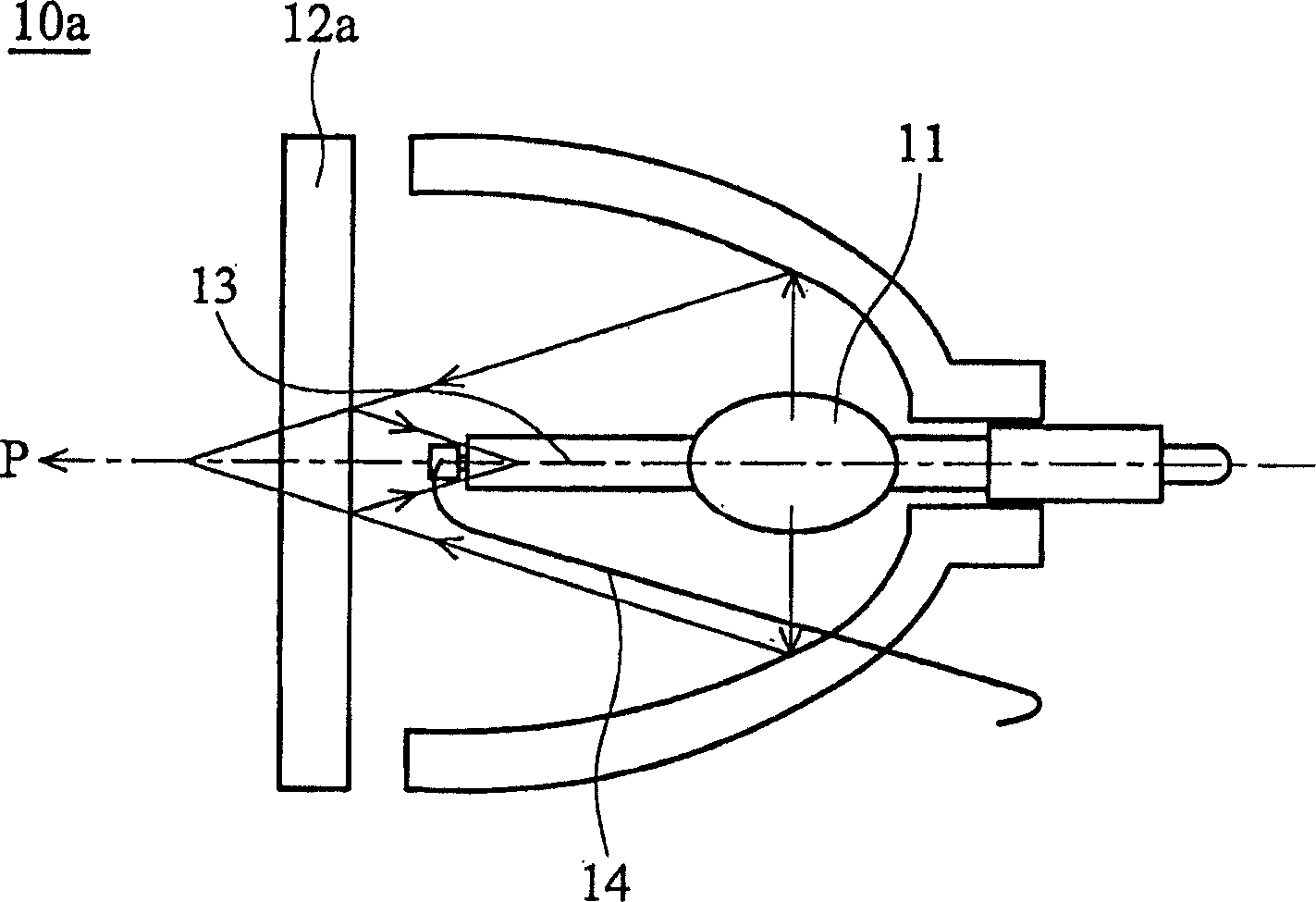
[0004] Also, refer to Figure 1a , on a projector (such as a digital light processing [DLP] projector), an invisible light reflector 12a (Invisible-LightFilter) will be installed in front of the light source 11 in the lighting device 10a to filter ultraviolet (UV) and infrared ( IR), but when the light passes through the invisible light reflector 12a, it will penetrate and reflect at the same time, so that the reflected light will focus on the lamp post 13 of the lighting device 10 and the vicinity of the light source 11, resulting in a phenomenon that the measured temperature is higher than the actual value
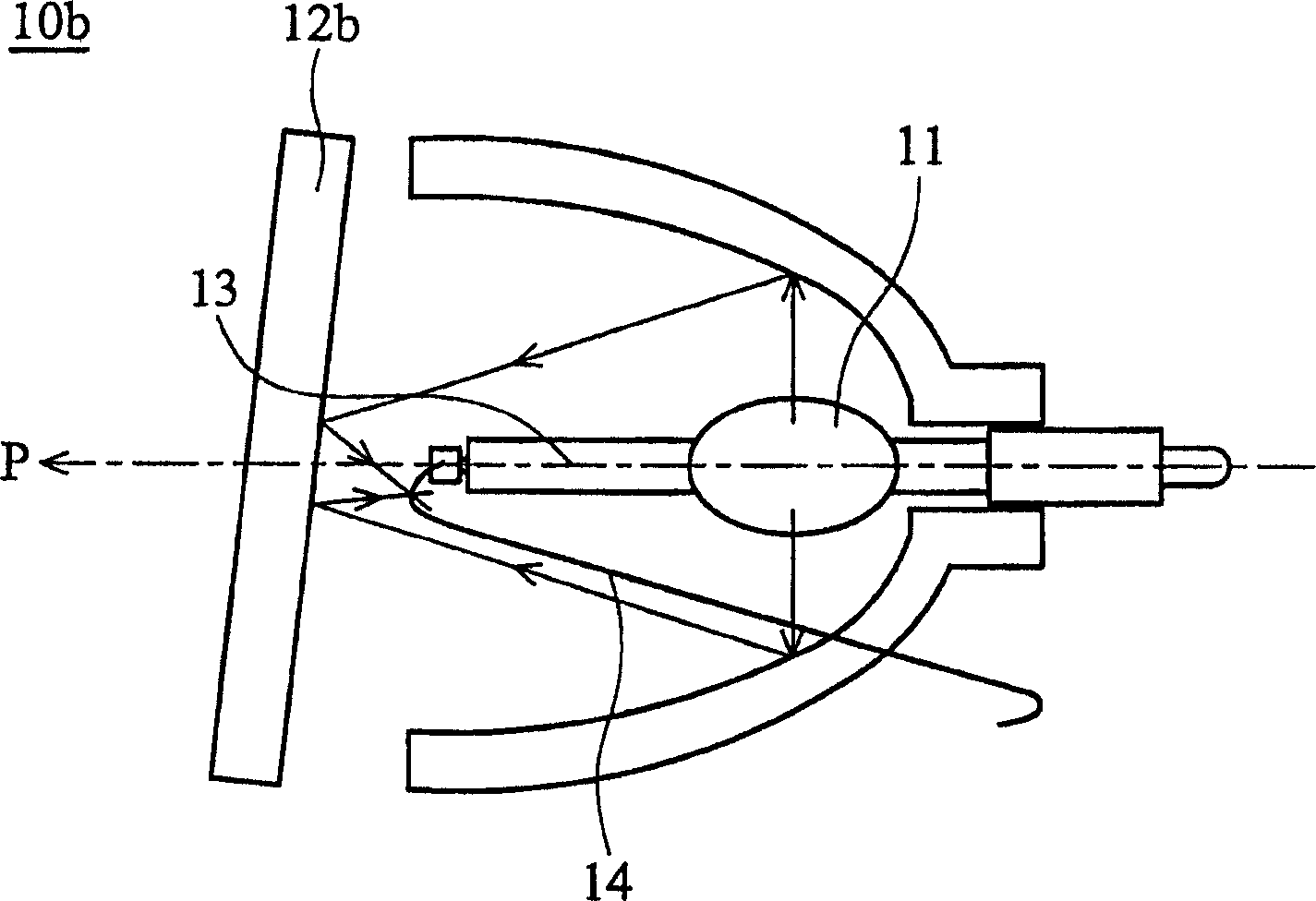
[0005] Furthermore, if Figure 1b As shown in Chinese Patent Application No. 03119907.0 "Projection Display Device with Invisible Light Reflecting Sheet that Can Disperse Heat Energy", the invisible light reflecting sheet 12b is set in such a way that its normal line and the light path have an acute angle, and the reflected light is easy to Focusing on the cathode line 14 of the lighting device 10 also causes the phenomenon that the measured temperature is higher than the actual value

Method used


Image

  • Projection display device, lighting device and temperature measuring method thereof
  • Projection display device, lighting device and temperature measuring method thereof
  • Projection display device, lighting device and temperature measuring method thereof

Examples


Embodiment Construction

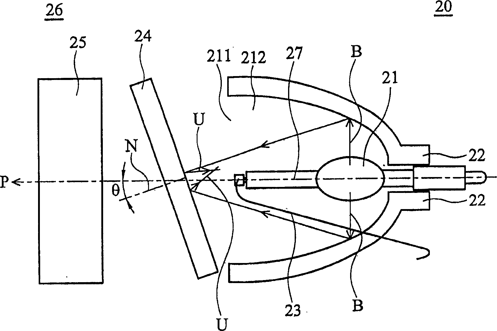
[0022] figure 2 It is the projection display device 26 of the present invention, which includes a light source 21, a reflector 22, a cathode line 23, an invisible light filter 24, an image module 25, and a lamp post 27, wherein the lamp post 27 and the light source 21 are electrically connected, and the light source 21, reflector 22, cathode line 23, invisible light filter 24, and lamp post 27 constitute the lighting device 20 of the present invention.

[0023] The light source 21 is used to generate an illuminating light beam B, and is arranged in the storage space 212 of the reflector 22; travel along an optical path P and exit the storage space 212 from the opening 211; figure 2 Among them, the reflector 22 is an ellipsoidal reflector, and the light source 21 is arranged on a focal point of the ellipsoidal reflector 22, and the above-mentioned optical path P is a major axis of the ellipsoidal reflector 22; The form of the cover is not limited, and the arrangement of the...


PUM


Abstract

This invention relates to a project device and illumination device and its temperature detecting method, wherein its method comprises the following steps: first, providing an illumination device with one invisible light filter pad to reflect the first light beam back to the illumination device generated by the illumination beam; then, setting at most two heat sensing detecting elements in the illumination device, wherein each element is set outside the first beam moving route; final, using each heat sensing detecting element to measure the temperature in the illumination device.

Description

technical field [0001] The invention relates to a projection display device, an illuminating device and a temperature measurement method thereof, in particular to a temperature measurement method capable of making lamp temperature measurement more accurate. Background technique [0002] In an existing projection display device (for example, a projector), in order to make the lighting device (for example, a mercury lamp) within a suitable temperature, it is necessary to measure the temperature of each key point in the lighting device. [0003] At present, in terms of temperature measurement, it is roughly divided into two types: the adhesion of thermal induction detection components (such as thermocouples, thermalcouples) and infrared (IR) measurement. When measuring temperature with thermocouples, it is necessary to measure the adhesion at each key point. If there are too many adhesion measurement points or improper routing, the wires will interfere with the cooling flow fie...

Claims


Application Information

Patent Timeline
IPC IPC(8): G01K7/02G03B21/00G03B21/14
Inventor 杨舜杰王邦吉魏宏任徐子桓吕圣章李长坚
Owner BENQ CORP
Learn More