Bored under-reamed filling pile and fabricating method therefor

The technology of a bottom-expanding cast-in-place pile and its manufacturing method is applied in the field of drilled-bottom-expanding cast-in-situ pile and its manufacture, which can solve the problems of poor uplift bearing capacity, troublesome construction, long pile body, etc., and achieve the purpose of increasing the bearing area of ​​pile ends, The effect of simple construction and small investment

Inactive Publication Date: 2005-07-06
SHANGHAI MUNICIPAL ENG DESIGN INST GRP
View PDF0 Cites 11 Cited by
  • Summary
  • Abstract
  • Description
  • Claims
  • Application Information

AI Technical Summary

Problems solved by technology

The commonly used solution in the past is to use straight-hole uplift piles to provide uplift resistance. This is currently recognized as one of the most reliable methods. However, due to the poor geology in Shanghai, which is a soft soil foundation, ordinary straight-hole drilling and grouting Pile can only rely on peripheral frictional resistance to provide uplift bearing capacity, the pile body to be used is generally longer, the number of piles is large, and the investment is large
In addition, combined with different foundation design requirements, there are also various pile types in the project, such as rammed gravel concrete pouring piles at the bottom of holes, rammed and expanded compacted cement-soil piles, post-grouting at the bottom of bored piles, artificial bottom expansion grouting Pile and large-diameter manual excavation pile, etc., but these pile types also have the disadvantages of poor uplift bearing capacity, large investment, troublesome construction, and long construction period. With the development of underground engineering construction in Shanghai, underground engineering The requirements for the uplift resistance of pile foundations are increasing day by day, and investors and construction parties are eager to provide a type of uplift pile with less investment, superior uplift performance and easy construction.

Method used


Image

  • Bored under-reamed filling pile and fabricating method therefor
  • Bored under-reamed filling pile and fabricating method therefor
  • Bored under-reamed filling pile and fabricating method therefor

Examples


Embodiment Construction

[0014] The present invention will be further described below in conjunction with the accompanying drawings and embodiments.

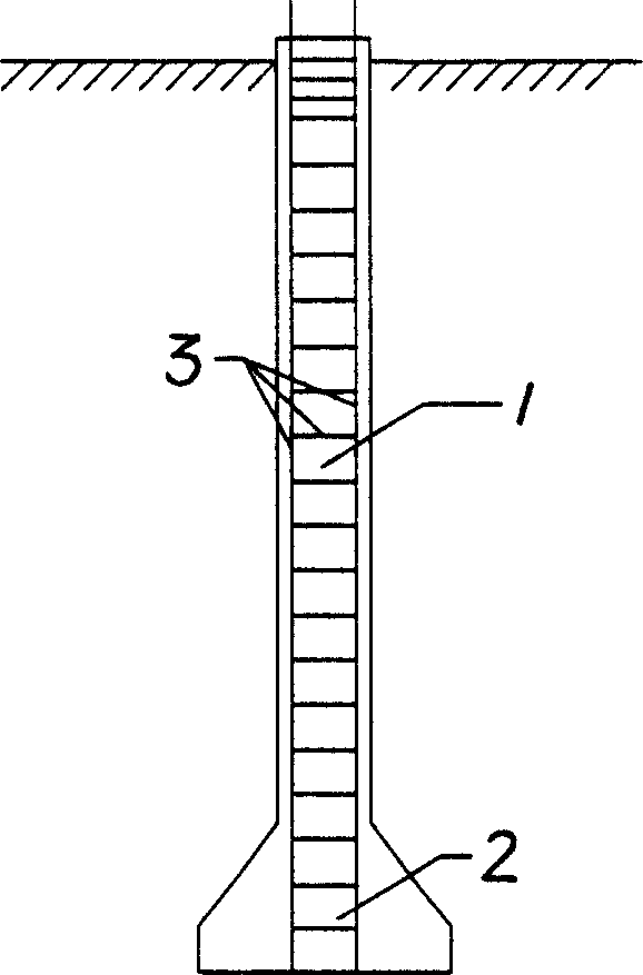
[0015] The present invention mainly comprises pile body 1, is characterized in that: described cast-in-place pile has an expanding head 2 at the bottom of pile body 1; The expanding head is concrete, its section is isosceles trapezoidal or conical, the inclination angle is greater than 30 degrees, the expanding head is 1.5-2.5 times of the pile diameter, and the whole pile is 30-70 meters long. A method for making cast-in-situ bored piles, characterized in that: the method for making cast-in-place piles includes the following steps: a, measuring and setting out, and fixing pile positions; b, laying casings, and putting a drilling rig in place; c, correcting The level of the grinding disc of the drilling rig and the verticality of the drill pipe; d, the hole is formed by positive circulation, and the drill bit is used to drill to the bottom of the hole, ...


PUM

PropertyMeasurementUnit
Diameteraaaaaaaaaa

Abstract

The invention discloses a bottom enlarged cast-in-place pile with dilled hole, wherein: the cast-in-place pile is arranged with an enlarged footing on the bottom. The enlarged footing of the invention formed by mechanical pressure and enlarged base drill bit enlarges the loaded area of the pile end and can provide more than two over three pulling-resistant force of the whole pile. The invention can satisfy the engineering demand of pulling-resistant load bearing, reduce the length and number of pile, simplify the construction and reduce cost.

Description

Technical field: [0001] The invention relates to the technical field of large-scale civil construction materials in the aspect of anti-floating and anti-tension of structures in engineering, in particular to a bored bottom-expanding cast-in-place pile and a manufacturing method thereof. Background technique: [0002] The underground water table in Shanghai area is relatively high, and the anti-floating of underground structures is often one of the important issues in underground engineering design. The commonly used solution in the past is to use straight-hole uplift piles to provide uplift resistance. This is currently recognized as one of the most reliable methods. However, due to the poor geology in Shanghai, which is a soft soil foundation, ordinary straight-hole drilling and grouting Pile can only rely on peripheral frictional resistance to provide uplift bearing capacity, the pile body to be used is generally longer, the number of piles is large, and the investment is ...

Claims


Application Information

Patent Timeline
IPC IPC(8): E02D5/44
Inventor 包旭范王海燕
Owner SHANGHAI MUNICIPAL ENG DESIGN INST GRP
Why Eureka
Try Eureka