
Display used to control computer host switch and its control method

A technology for controlling computers and displays, applied in computing, instruments, measuring devices, etc., can solve the problems of high production cost and low efficiency of power management signal transmission process

Inactive Publication Date: 2005-06-08
ACER INC
View PDF1 Cites 18 Cited by
  • Summary
  • Abstract
  • Description
  • Claims
  • Application Information

AI Technical Summary

Problems solved by technology

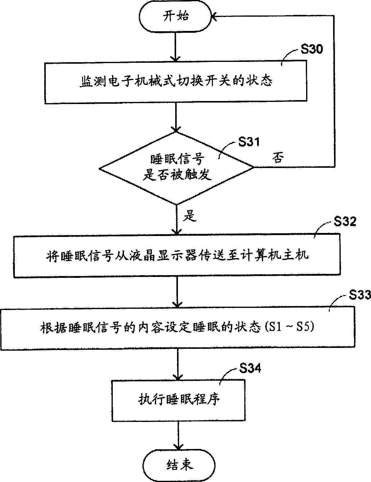
[0010] The main purpose of the present invention is to provide a display and its control method for controlling the switch of the computer mainframe, so as to solve the disadvantages of high production cost and low efficiency of the power management signal transmission process caused by the need for a specially designed USB hub for traditional displays.

Method used


Image

  • Display used to control computer host switch and its control method
  • Display used to control computer host switch and its control method
  • Display used to control computer host switch and its control method

Examples


Embodiment Construction

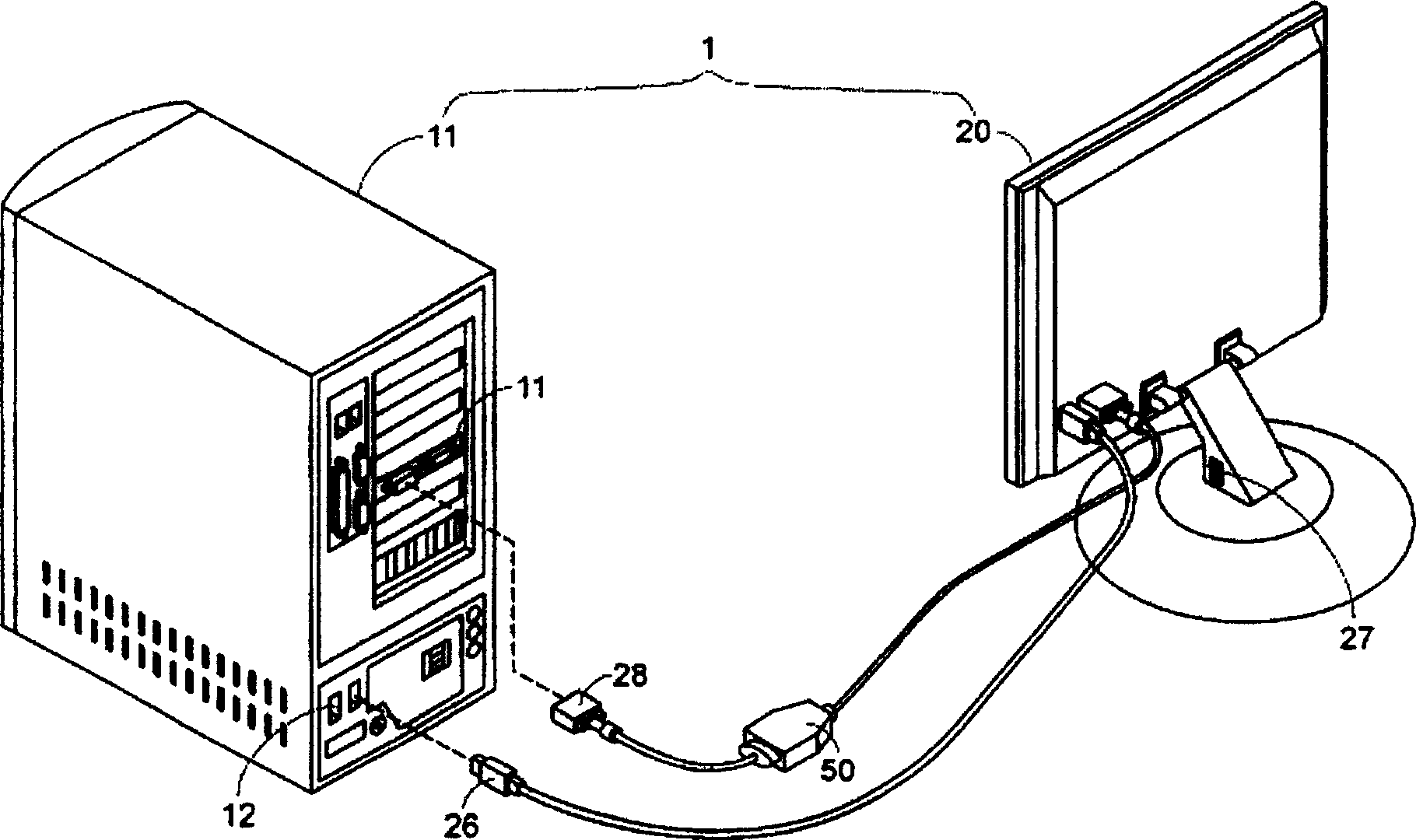
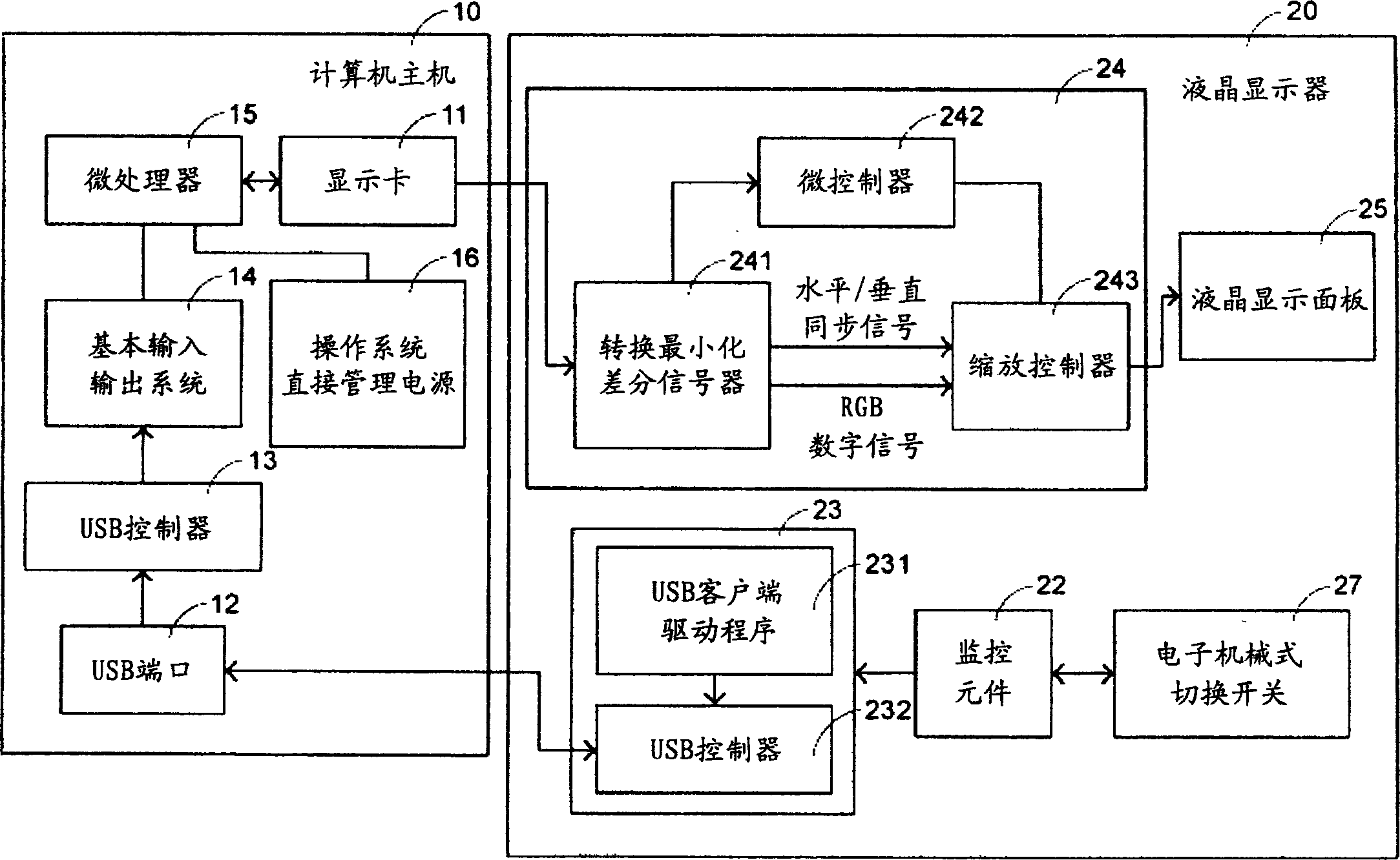
[0034] see figure 1, which is a schematic structural diagram of a computer system in a preferred embodiment of the present invention. It can be seen from the figure that the computer system 1 of the present invention mainly includes a computer host 10 and a liquid crystal display 20 . The host computer 10 can be plugged with multiple hardware devices, such as a display card 11 and so on. The liquid crystal display 20 has a switch component, such as a switch 27, which can be implemented as a multi-segment electromechanical switch. The liquid crystal display 20 is electrically connected to the display card 11 through the video connector 28 of the digital interactive cable (DVI cable) 50 , and the USB connector 26 is electrically connected to the USB port 12 of the host computer 10 . In this way, the user can control the computer mainframe 10 to start or shut down by pressing the electromechanical switch 27 .

[0035] see again figure 2 , which is a schematic block diagram of...


PUM


Abstract

A display for controlling switch of main frame and its control method. The switch triggered by external force is for controlling a system main frame which comprise of a processing component. The display includes: switching component generating all switching conditions being triggered by external force; a monitoring component connecting to the switching component for monitoring its switching condition and judging ether the management event of electric source has been triggered in accordance with the switching condition, and a transmitting component connecting to the monitoring one, generating a signal of electric source and transmitting it to the system, in accordance with the judged result, making the processing component do the corresponding operations of starting up or shutting down to the system main frame according to the signal.

Description

technical field [0001] The invention relates to a display and its control method, in particular to a display which can be used to control the switch of a computer host and its control method. Background technique [0002] Generally speaking, a computer system needs to use a power management system (power management system) to realize the function of reserve power. Therefore, on December 22, 1996, Intel, Microsoft, and Toshiba jointly developed and published an Advanced Configuration and Power Interface (ACPI) standard, which mainly integrates power management functions into the operating system, through A unified interface to control the power operation of all hardware to improve power management performance and speed up the processing speed of the computer system. [0003] According to the definition of the Advanced Configuration and Power Interface (ACPI) standard, the power management of the computer system can be divided into six modes (S0-S5): S0 is the normal mode of ...

Claims


Application Information

Patent Timeline
IPC IPC(8): G06F1/16G06F1/26
Inventor 欧智平
Owner ACER INC
Learn More