
Direct current electrostatic dust collection method and dust collector

An electrostatic precipitator and electrostatic precipitator technology, applied in the field of electrostatic precipitator, can solve problems such as waste of electric energy, difficulty in ensuring operational reliability, and excessive steel materials

Inactive Publication Date: 2005-06-01
石家庄市自动化研究所
View PDF0 Cites 3 Cited by
  • Summary
  • Abstract
  • Description
  • Claims
  • Application Information

AI Technical Summary

Problems solved by technology

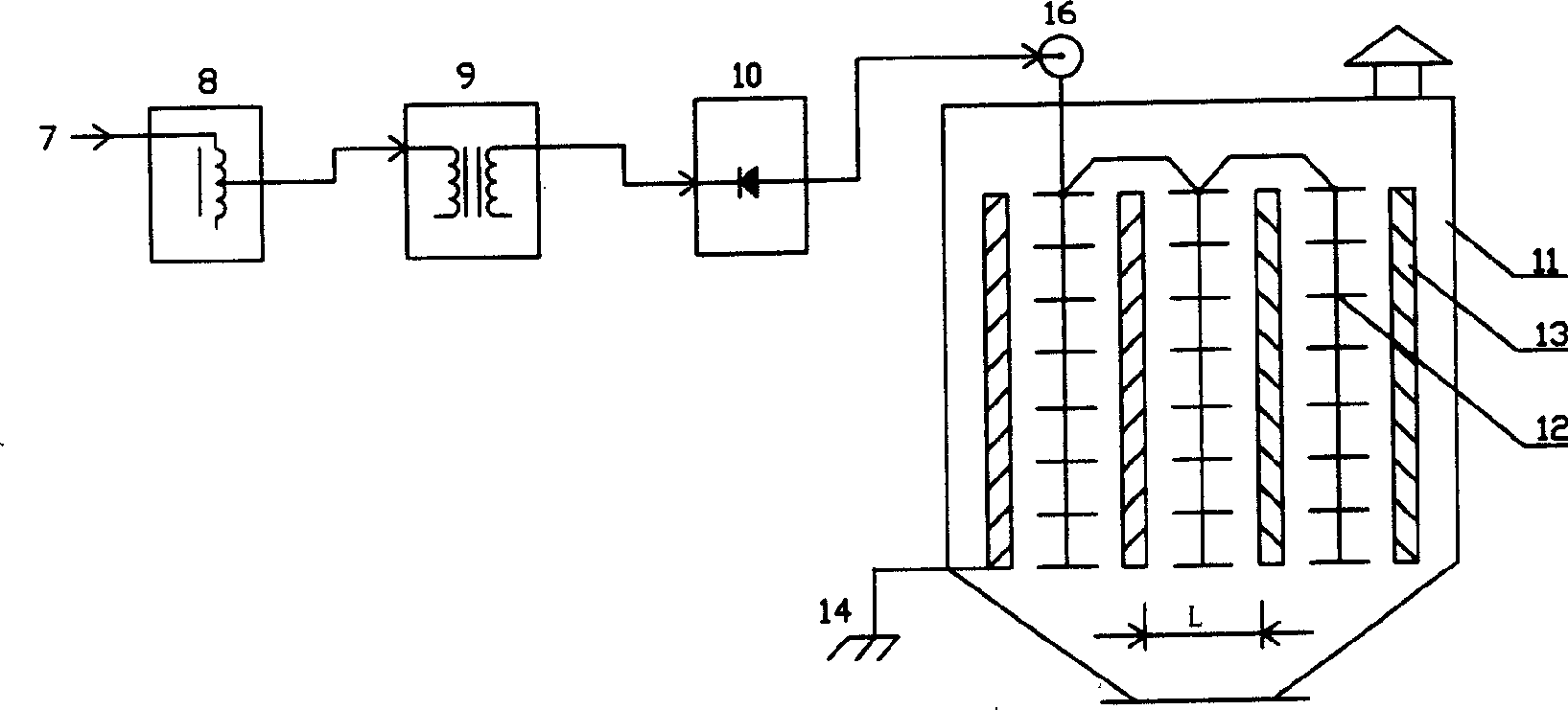
In order to make up for the loss in this period, it is necessary to increase the supply voltage value, but due to the severe nonlinearity of the load curve 3, the load curve 3 will produce a large peak, and the high-density free electrons that form the current peak cannot be used to effectively charge the passing dust particles in a short time, so a large number of remaining electrons fly directly from the corona pole line 12 to the dust collecting plate 13, forming A lot of waste of electricity
[0005] On the other hand, due to the pursuit of the best electric spark rate, the rectification power supply that must be used has an instantaneous maximum voltage, and the homopolar distance L inside the electrostatic precipitator cannot be widened arbitrarily. Generally, L=200mm-400mm or so, Otherwise, it is difficult to ensure the reliability of operation, so the structure of the electrostatic precipitator body consumes more steel

Method used


Image

  • Direct current electrostatic dust collection method and dust collector
  • Direct current electrostatic dust collection method and dust collector
  • Direct current electrostatic dust collection method and dust collector

Examples


Embodiment Construction

[0029] Embodiments of the present invention will be described below in conjunction with the accompanying drawings.

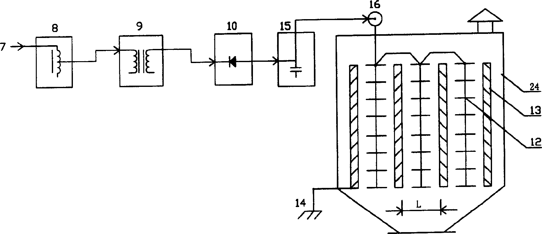
[0030] Such as figure 2 As shown, the DC electrostatic precipitator 24 of the present invention includes a power input 7, a regulator 8, a power frequency step-up transformer 9, a power frequency high-voltage rectifier (silicon stack) 10, and a high-voltage filter 15, which can be made by ordinary low-frequency capacitors. The electrostatic precipitator 24 body has a power pole line 12, a dust collection pole plate 13, a ground wire terminal 14, and a high-voltage terminal 16. The regulator 8 can be a voltage regulator or a bidirectional silicon controlled rectifier, and the high-voltage filter 15 can be an ordinary low-frequency Capacitors are made, and the distance L between the 13 poles of the dust-collecting plates is preferably 400mm-800mm. The voltage of the 50Hz-50Hz power supply 7 controlled by the regulator 8 is turned into a high voltage by the boost...


PUM

PropertyMeasurementUnit
Intervalaaaaaaaaaa

Abstract

The DC electrostatic dedusting process includes the following successive steps: regulating the input power source into industrial frequency power source, stepping up the industrial frequency voltage with the industrial frequency step-up transformer, rectifying in the industrial frequency high voltage rectifier, high voltage filtering in the high voltage filter, and applying the high voltage DC voltage to the dust collecting plate via the high voltage terminals. The DC electrostatic deduster has high frequency inversing link comprising low voltage rectifier, low frequency filter, high frequency inverter, high frequency step-up transformer, high frequency high voltage rectifier and high frequency high voltage filter connected successively. The present invention has obvious power and steel saving effect.

Description

technical field [0001] The invention relates to an electrostatic precipitator and method applied in the technical field of electrostatic precipitator for environmental protection, in particular to a DC electrostatic precipitator and a dust removal method. Background technique [0002] At present, in the field of electrostatic dust removal technology, the "best electric spark rate dust removal method" is widely used at home and abroad. This dust removal method can be seen in the book "dust collector", published by China Architecture Press. It is pointed out in the book that in 1950, American scholar White proposed the concept of the optimal degree of electric spark in electrostatic precipitator, that is, when the power supply increases to a certain level, the number of electric field discharges increases, and the dust removal efficiency has a maximum value. Due to the frequent high-voltage ignition process, it is required that the power supply can only use power frequency rec...

Claims


Application Information

Patent Timeline
IPC IPC(8): B03C3/66
Inventor 赵富葛淑欣于文海何健李泽民
Owner 石家庄市自动化研究所
Learn More