Optical switch and production method therefor, information transmission device using
An optical switch and information transmission technology, applied in optics, microstructure devices composed of deformable elements, optical elements, etc., can solve problems such as difficulties and unstable translation control
- Summary
- Abstract
- Description
- Claims
- Application Information
AI Technical Summary
Problems solved by technology
Method used
Image
Examples
Embodiment approach 1
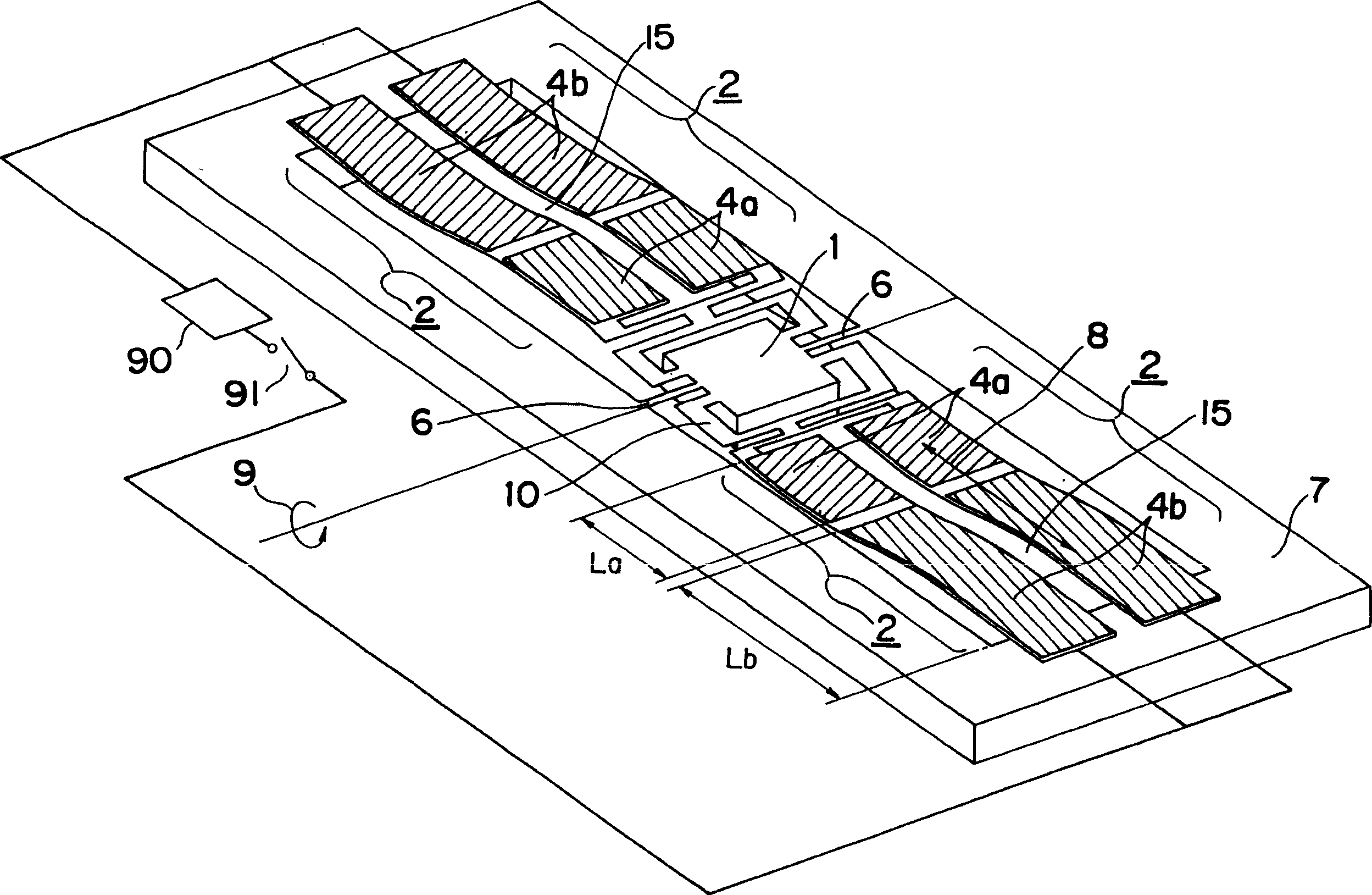
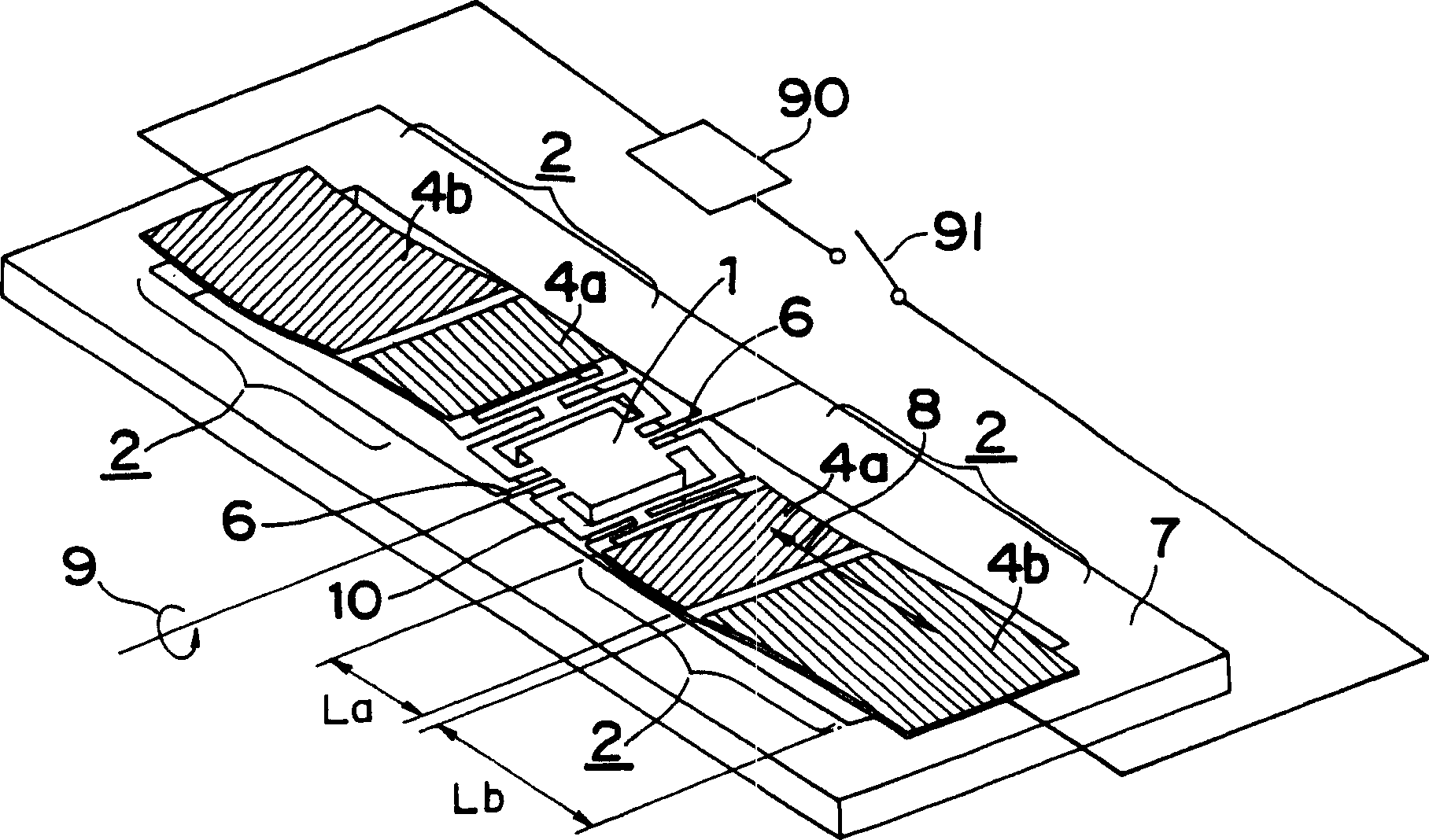
[0053] Figure 1A is a perspective view of an optical switch according to Embodiment 1 of the present invention, Figure 1B It is a perspective view of an optical switch according to a modified example of Embodiment 1 of the present invention. Figure 2A It is a cross-sectional view showing a part of the optical switch according to Embodiment 1 of the present invention.
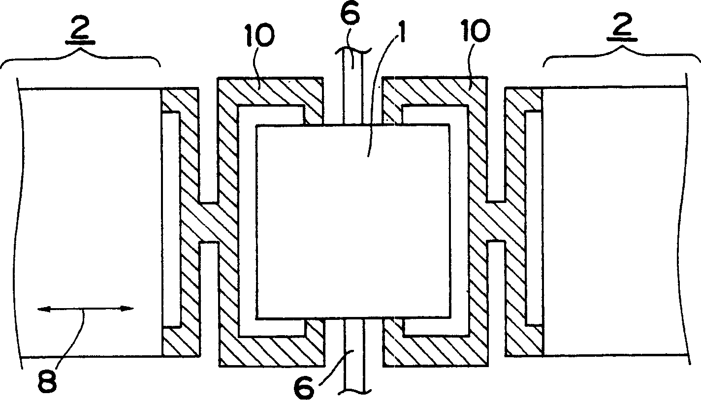
[0054] On the substrate 7, the reflective element 1, the thin-film piezoelectric body 3 arranged symmetrically with respect to the rotation axis 9 on both sides of the reflective element 1, and the first thin-film piezoelectric body arranged on the reflective element side on the upper surface of each thin-film piezoelectric body 3 The upper electrode 4a, the second upper electrode 4b arranged away from the first upper electrode 4a on the opposite side of the reflection element on the upper surface of each thin film piezoelectric body 3, the lower electrode 4c arranged on the lower surface of each thin film p...
Embodiment approach 2
[0080] Figure 5A It is a perspective view of an optical switch according to Embodiment 2 of the present invention. In this second embodiment, along the surface of the substrate that constitutes the thin-film piezoelectric body, Figure 5A The reflective surface 1b is provided in the normal direction of the substrate surface, and the reflective element 1A is driven in the normal direction of the substrate surface. Each constituent element is basically the same as that described as the detailed description of Embodiment 1. Figure 1A It is the same, and the same code|symbol is given to the same component. The thin-film piezoelectric body 3 , electrodes 4 , and elastic body 5 constituting the piezoelectric element 2 have the same configuration as those in Embodiment 1, and therefore are not shown here. The electrode 4 is composed of two upper electrodes 4a, 4b similarly to the first embodiment, here, for the sake of simplification, it is shown as one electrode, but actually i...
Embodiment approach 3
[0090] Figure 7A , Figure 7B It is a top view and a side view of the information transmission device in Embodiment 3 of this invention. In Embodiment 3, the actuator is composed of a plurality of rows of piezoelectric elements 2 arranged in parallel along its longitudinal direction 8 , and a plurality of optical transmission lines 11 are arranged corresponding to the rows of the plurality of piezoelectric elements 2 . By employing such a configuration, a plurality of optical transmission lines 11 can be arranged at high density, and an optical switch including a plurality of optical transmission lines can be compactly configured.
[0091] In particular, an optical fiber used as an optical transmission line is generally used by bundling a plurality of fibers, and a connector at the terminal thereof is generally arranged in parallel with each fiber. Figure 7A In this case, a plurality of optical transmission lines 11 (specifically, transmission lines 11 a and 11 b ) are arr...
PUM
 Abstract
Description
Claims
Application Information
 - R&D
- Intellectual Property
- Life Sciences
- Materials
- Tech Scout
- Unparalleled Data Quality
- Higher Quality Content
- 60% Fewer Hallucinations
Browse by: Latest US Patents, China's latest patents, Technical Efficacy Thesaurus, Application Domain, Technology Topic, Popular Technical Reports.
© 2025 PatSnap. All rights reserved.Legal|Privacy policy|Modern Slavery Act Transparency Statement|Sitemap|About US| Contact US: help@patsnap.com


