
Method for measuring factory harmonic wave and measuring instrument

A harmonic and factory technology, applied in the field of measuring harmonic system harmonics in factories, can solve the problem that the harmonic synchronous dynamic change characteristics of harmonic monitoring points cannot be measured, and the network space transmission characteristics of harmonic current systems of harmonic source electrical equipment cannot be measured. , system equipment network compatibility failure, etc.

Inactive Publication Date: 2005-05-04
贺守正
View PDF3 Cites 26 Cited by
  • Summary
  • Abstract
  • Description
  • Claims
  • Application Information

AI Technical Summary

Problems solved by technology

[0005] The disadvantage of the existing technology is that in different harmonic processes, the harmonic dynamic change characteristics of each harmonic monitoring point, the system harmonic impedance characteristics and the harmonic current amplification factor are measured separately, and the harmonic synchronization dynamics of each harmonic monitoring point cannot be measured. Change characteristics; it is impossible to measure the time variation of the harmonic current level of the harmonic source electrical equipment, the distribution of the system network space change and the time variation distribution of the system harmonic voltage drop level, so it is impossible to measure the harmonic current of the harmonic source electrical equipment in the system network space Transmission characteristics, and the source and quantity of harmonics at each monitoring point, the harmonics of the factory harmonic system are still unpredictable and unpredictable
[0006] The disadvantage of the existing technology is that the factory uses a tuned filter to absorb the harmonic current of the harmonic source electrical equipment and reduce the harmonic injection of the common connection point, but it cannot measure the time change of the harmonic current level in the system network space before and after the filter is put into the system, and the system network The distribution of spatial changes; the filter parameters that make the harmonic source electrical equipment run compatible with the system harmonic compatible power cannot be measured, so when the operating power of the harmonic source electrical equipment is lower than the system allowable power or multiple harmonic source electrical equipment are superimposed During the operation process, the harmonic current at the common connection point exceeds the limit value standard, randomly causing system equipment network compatibility failures, reducing the production safety, economic quality and benefits of the factory harmonic system
[0007] The disadvantage of the existing technology is that it cannot simultaneously measure the time change of the bus harmonic level of the common connection point of the harmonic system of each factory and the common connection point of the power supply system, and the spatial change distribution characteristics of each common connection point and the common connection point of the bus.

Method used


Image

  • Method for measuring factory harmonic wave and measuring instrument
  • Method for measuring factory harmonic wave and measuring instrument

Examples


Embodiment 1

[0041] The embodiment is described in comparison with the prior art. The embodiment does not discuss the calculation of the power of the electrical equipment that is allowed to access the harmonic source of the power supply system, which does not belong to the description scope of the present invention.

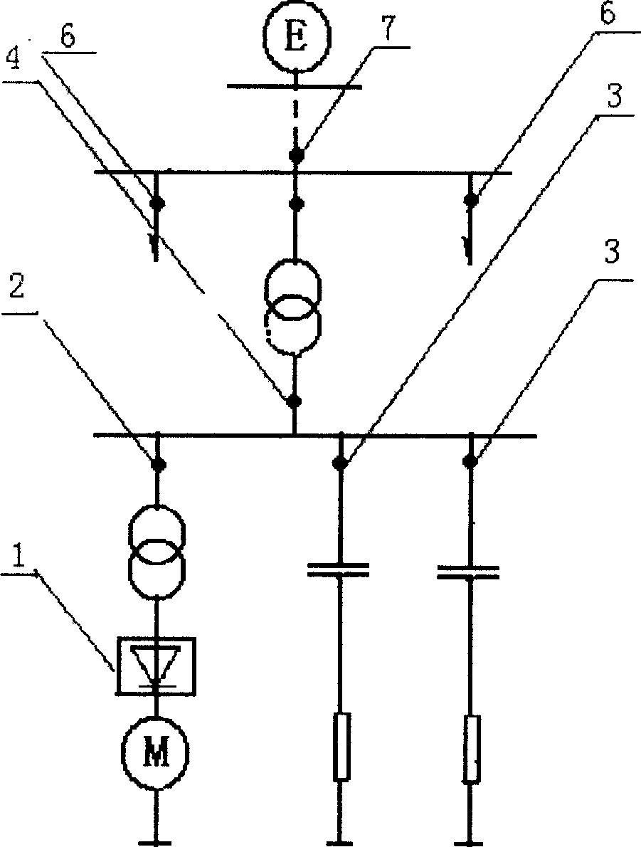
[0042] A rolling mill powered by a converter (1) is used in the rolling mill, and two sets of filters (3) are used on the same busbar of the rolling mill to absorb part of the harmonic current of the converter. However, during the operation of the converter, the The harmonic current at the common connection point (4) exceeds the limit value standard, the reactive power compensation capacitor is overheated and damaged, and the electrical equipment on the same bus is randomly caused to fail.

[0043] The reason is that the prior art cannot measure synchronously in the same steel rolling process before and after the filter is put into operation, each harmonic monitoring point in...

example 2

[0064] Measure the harmonics of the harmonic system of the factory using more than two harmonic source electrical equipment. The difference from the above example is that the transfer function calculation is performed on the results of the Fourier analysis. It is only for the operation of a single harmonic source electrical equipment, or multiple During the operation of the station, only a single harmonic source electrical equipment bus connection point has the Fourier analysis results of the short time course of the harmonic current, and calculates the transfer function, and simultaneously measures the time change of the harmonic current level at the harmonic source electrical equipment bus connection point , The distribution of system network space changes, that is, the time change distribution characteristics of the harmonic current at the bus connection point of two harmonic source electrical equipment at the common connection point of the system network space and the filter...

example 3

[0066] The power supply department uses the common connection point (4) (6) as a harmonic current source to measure the harmonic current at the common connection point of each factory and the harmonic current and harmonic voltage drop superposition of the busbar (7) at the common connection point of the power supply system . In the prior art, sampling is performed at each public connection point at long intervals during the production process of the factory, and the harmonic injection is evaluated by a 95% probability statistical method, and any sampling probability statistical method has no repeatable results. The method of the invention is to measure the common connection point of each factory synchronously and continuously and the harmonic current and the harmonic voltage drop of the common connection point.


PUM


Abstract

This invention relates to the method of measuring factory harmonic wave and measuring apparatus. The measuring of factory harmonic wave is measuring the system harmonic wave of electric equipment, filter factory harmonic wave source, and the factory harmonic wave that connected with the power supply system. The distribution of harmonic wave process and harmonic wave current level time changes of harmonic wave source electric equipment will be measured, and the filtering parameter of the harmonic wave source electric equipment and systematic equipment network that includes compatible power and compatible running with power supply system, filter and the mutual bus bar electric equipment will also be measured. The factory that uses this method can directly measure and manage the system harmonic wave of the factory harmonic wave. This invention synchronizing measuring the harmonic current and harmonic voltage drop level time changing of the common junction and its bus bar, and the distribution feature of the common junctions.

Description

Technical field [0001] The technical field to which the invention relates is the measurement of plant harmonic system harmonics. Factory harmonic system harmonics belong to the power system harmonics. Background technique [0002] Existing patent documents for measuring power system harmonics include "Power System Harmonic Measurement Method and Measuring Instrument" (89105302.6), "Power System Harmonic Measurement Method Using Computer" (92106527.2), "Power System Harmonic Quantitative Measurement Method and Measuring Instruments" (98110414.2). The purpose of the invention is to accurately and quantitatively measure the harmonic current and harmonic voltage drop dynamic change characteristics of the power system harmonic network space harmonic monitoring points, the system harmonic impedance characteristics and the harmonic current amplification and absorption characteristics. [0003] The factory harmonic source electrical equipment, filter and power supply system are co...

Claims


Application Information

Patent Timeline
Patent Type & Authority Applications(China)
IPC IPC(8): G01R23/16
Inventor 贺守正
Owner 贺守正
Learn More