
Three-phase power factor correcting circuit with AC boosting mode

A technology of three-phase power and correction circuit, which is applied in the field of power electronics, can solve problems such as technical difficulty and difficulty in realizing harmonic suppression of three-phase circuits

Inactive Publication Date: 2005-04-27
BEIJING UNIV OF TECH
View PDF0 Cites 18 Cited by
  • Summary
  • Abstract
  • Description
  • Claims
  • Application Information

AI Technical Summary

Problems solved by technology

However, due to the technical difficulty of the three-phase power factor correction circuit, it is difficult to realize the harmonic suppression of the three-phase circuit by the simple combination of the single-phase power factor correction circuit
Foreign scholars are only at the preliminary research stage. The working mode of the circuit generally adopts the inductive current discontinuous mode. The power switch of the circuit bears a relatively large current and voltage stress, which is only suitable for three-phase low-power equipment with stable loads. For the inductive current Continuous 10KW high-power three-phase power factor correction circuit has not yet been published

Method used


Image

  • Three-phase power factor correcting circuit with AC boosting mode
  • Three-phase power factor correcting circuit with AC boosting mode
  • Three-phase power factor correcting circuit with AC boosting mode

Examples


Embodiment Construction

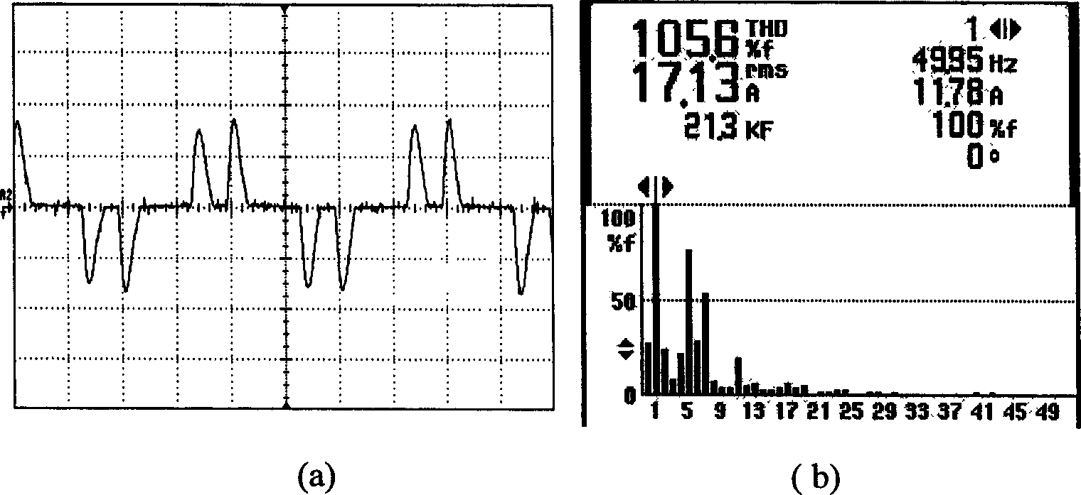
[0026] By adopting the design of the present invention, a 400A arc welding inverter power supply with harmonic suppression function is developed. Its input stage adopts a three-phase power factor correction circuit of AC boost mode (inductance value 3mL, DC side capacitor C1 , C2 is 2200uF, the rectifier bridge adopts diode rectification with fast recovery characteristics, the base part of the bidirectional power switch module is IGBT (BSM150GB120DN2)), the power output range is 10kW-15kW, and the power converter adopts a full-bridge inverter circuit. Arc welding inverter power supply with low harmonic distortion is the development trend of welding power supply. In general, this welding machine includes two parts: one is a harmonic suppressor, which can also be called a voltage pre-regulator or a power factor correction stage, and the other is a power converter, which is a traditional arc welding inverter power supply. Remove the input rectifier filter part. These two parts are ea...


PUM


Abstract

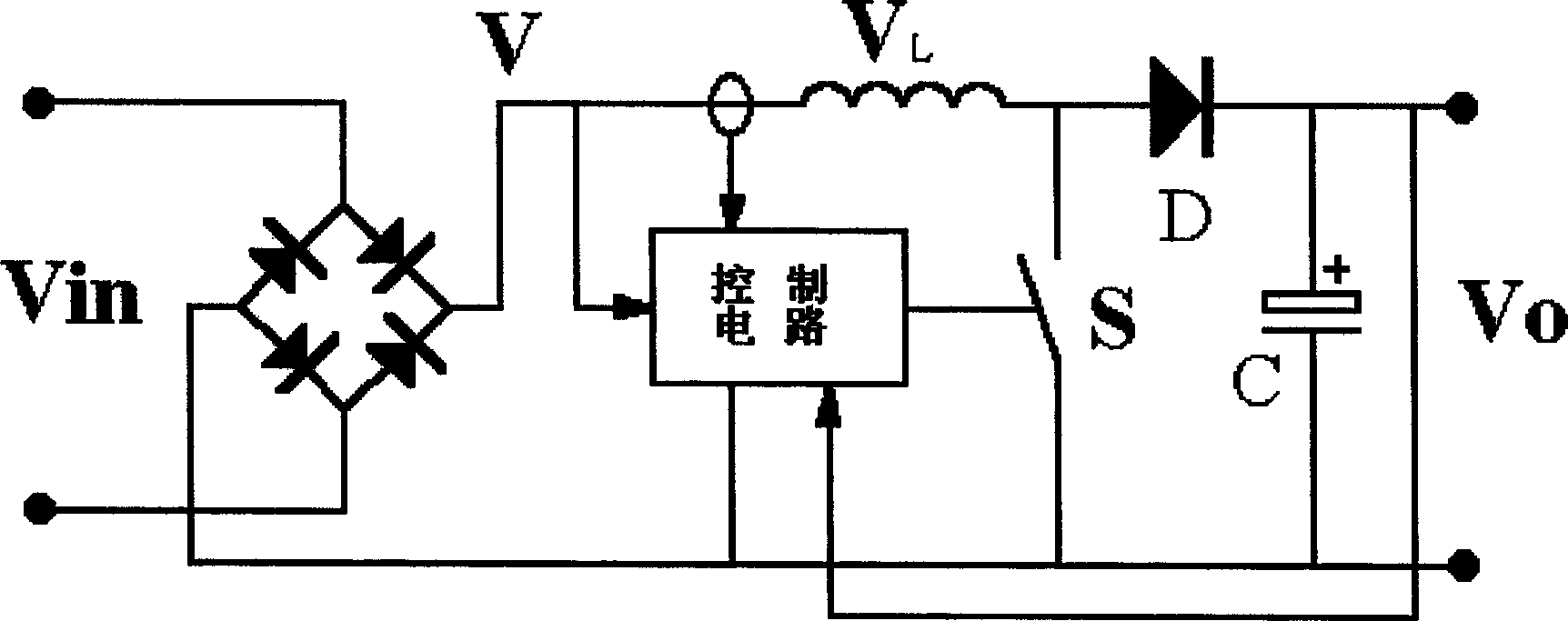
The triphase AC step-up type power factor correcting circuit is used in converter power supply. Up to now, there is no 10 KW level great power triphase power factor correcting circuit. The present invention features the Y-type connection to the triphase power network, and the power factor correcting circuit consists of three inductors, six diodes to constitute bridge rectifier and two capacitors connected serially. The present invention has simplified control, and can raise the power factor of arc welding converter power supply with capacitor filter rectifier circuit as input stage from 0.6-0.7 to 0.98-1.

Description

Technical field [0001] This technology belongs to the field of power electronics technology, and its main application range is inverter arc welding power supplies and other inverter power supplies. Background technique [0002] With the acceleration of industrialization worldwide, energy and environmental protection have received more and more attention. In addition to the rational development of energy and the search for new energy to solve the energy problem, tapping the potential and improving the efficiency of energy utilization has also been mentioned as an important position in various industries. Environmental protection is no longer limited to the treatment of waste gas, waste water, waste residue, and noise. Electromagnetic pollution has been identified as the fifth largest source of pollution. [0003] Harmonic pollution and radio frequency pollution are typical electromagnetic pollution. Electrical processing of materials is the industry that consumes the most power. F...

Claims


Application Information

Patent Timeline
Patent Type & Authority Applications(China)
IPC IPC(8): H02J3/18H02M1/14H02M7/12
CPCY02E40/30
Inventor 陈树君殷树言卢振洋李西恭曾华
Owner BEIJING UNIV OF TECH
Learn More