
Two-wheel motorcycle

A technology of two-wheeled motorcycles and rear wheels, applied to bicycle accessories, fuel air filters, charging systems, etc., can solve problems such as inability to ensure volume, and achieve the effect of increasing suction capacity and reducing suction resistance

Active Publication Date: 2005-04-20
YAMAHA MOTOR CO LTD
View PDF1 Cites 8 Cited by
  • Summary
  • Abstract
  • Description
  • Claims
  • Application Information

AI Technical Summary

Problems solved by technology

[0003] However, for example, when the air filter housing is arranged above the transmission housing of the combined swing type power unit or on one side of the rear wheel, a sufficient volume cannot be ensured, so openings must be provided in multiple places for suction. gas

Method used


Image

  • Two-wheel motorcycle
  • Two-wheel motorcycle
  • Two-wheel motorcycle

Examples


Embodiment Construction

[0024] Hereinafter, an embodiment of the air intake device for a small motorcycle according to the present invention will be described, but the present invention is not limited to this embodiment. In addition, the embodiment of the present invention shows the best mode of the present invention, and the terms of the present invention are not limited thereto.

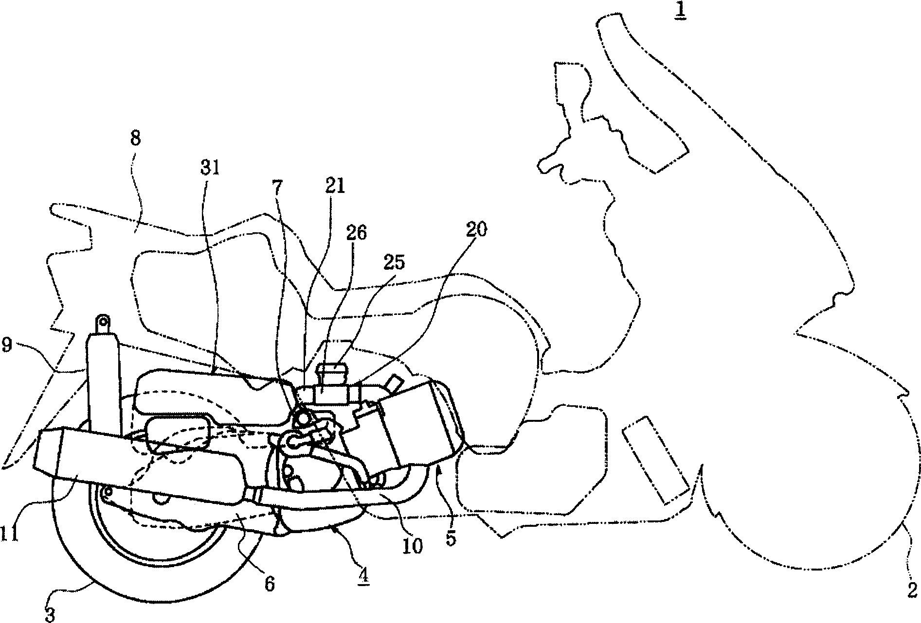
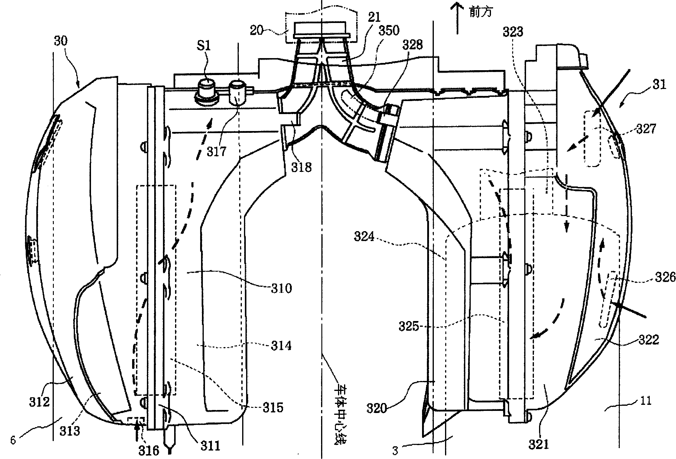
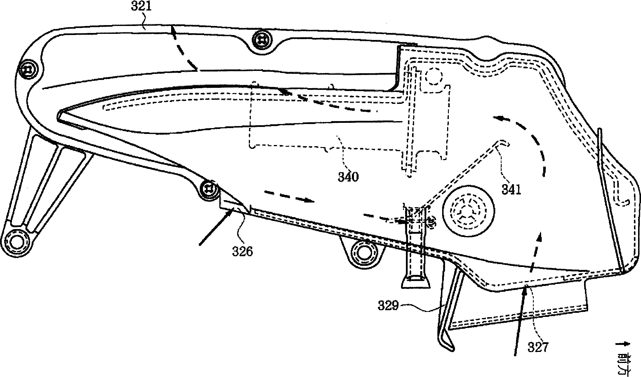
[0025] figure 1 It is a side view of a small two-wheeled motorcycle, figure 2 is the top view of the suction device, image 3 is a side view of the air filter housing, Figure 4 is a cross-sectional view of the air filter housing, Figure 5 is a side view of the housing body, Image 6 is a side view of the housing.

[0026] In these figures, reference numeral 1 denotes a small two-wheeled motorcycle according to the present embodiment. The two-wheeled motorcycle 1 is equipped with a front wheel 2 and a rear wheel 3, and the rear wheel 3 has adopted a structure driven by a combined swing type power unit 4.

[0027]...


PUM


Abstract

The present invention is an air intake device for a two-wheeled motorcycle, which is formed in an air filter housing divided into an upstream side air chamber and a downstream side air chamber by an air filter element, and the lower part of the air filter housing has a The lower opening is further provided with a rib that surrounds at least a part of the circumference of the lower opening and protrudes downward from the air filter case. It is possible to prevent rainwater and muddy water from being sucked into the air filter housing while reducing the suction resistance.

Description

technical field [0001] The invention relates to an air suction device for a two-wheeled motorcycle. Background technique [0002] In the past, for example, the air filter mounted above the transmission housing of the combined swing power unit used to form an upstream side air chamber and a downstream side air chamber in the air filter housing, and a The structure of the air filter element. The upstream side air chamber is opened to the atmosphere through an air inlet located at an outer end portion in the vehicle width direction of the air filter housing. (For example, Patent Document 1: Japanese Patent Laid-Open No. 2001-63665) [0003] However, for example, when the air filter housing is arranged above the transmission housing of the combined swing type power unit, or on one side of the rear wheel, etc., sufficient capacity cannot be ensured, so openings must be provided in multiple places for suction. gas. [0004] The present inventi...

Claims


Application Information

Patent Timeline
Patent Type & Authority Applications(China)
IPC IPC(8): B62J99/00F02M35/024F02M35/08F02M35/16
Inventor 松坂茂
Owner YAMAHA MOTOR CO LTD
Learn More