
Locking pin having anti-pumping device

A technology of anti-jumping and locking pins, which is applied in the direction of railway couplings, railway car body parts, transportation and packaging, etc., can solve problems such as detachment and anti-jump failure, and achieve convenient maintenance, reliable anti-jumping effect, and simple structure Effect

Inactive Publication Date: 2005-04-13
张书叙
View PDF0 Cites 0 Cited by
  • Summary
  • Abstract
  • Description
  • Claims
  • Application Information

AI Technical Summary

Problems solved by technology

Once there is an acceleration in the direction of the knuckle tongue, a reverse eccentric force will be generated, and when this force is sufficient to overcome the eccentric force of the upper lock pin, the top of the upper lock pin rod can be separated from the anti-jump platform of the hook cavity, resulting in anti-jump fail
Once the anti-jumping fails, the worn couplers in each part are under the heavy-duty traction state, the hook lock iron is strongly squeezed, and the upward component force is generated instantaneously during operation, which is enough to make the coupler lock iron and the upper lock pin jump up to the unlocking position , resulting in a split hook

Method used


Image

  • Locking pin having anti-pumping device
  • Locking pin having anti-pumping device
  • Locking pin having anti-pumping device

Examples


Embodiment Construction

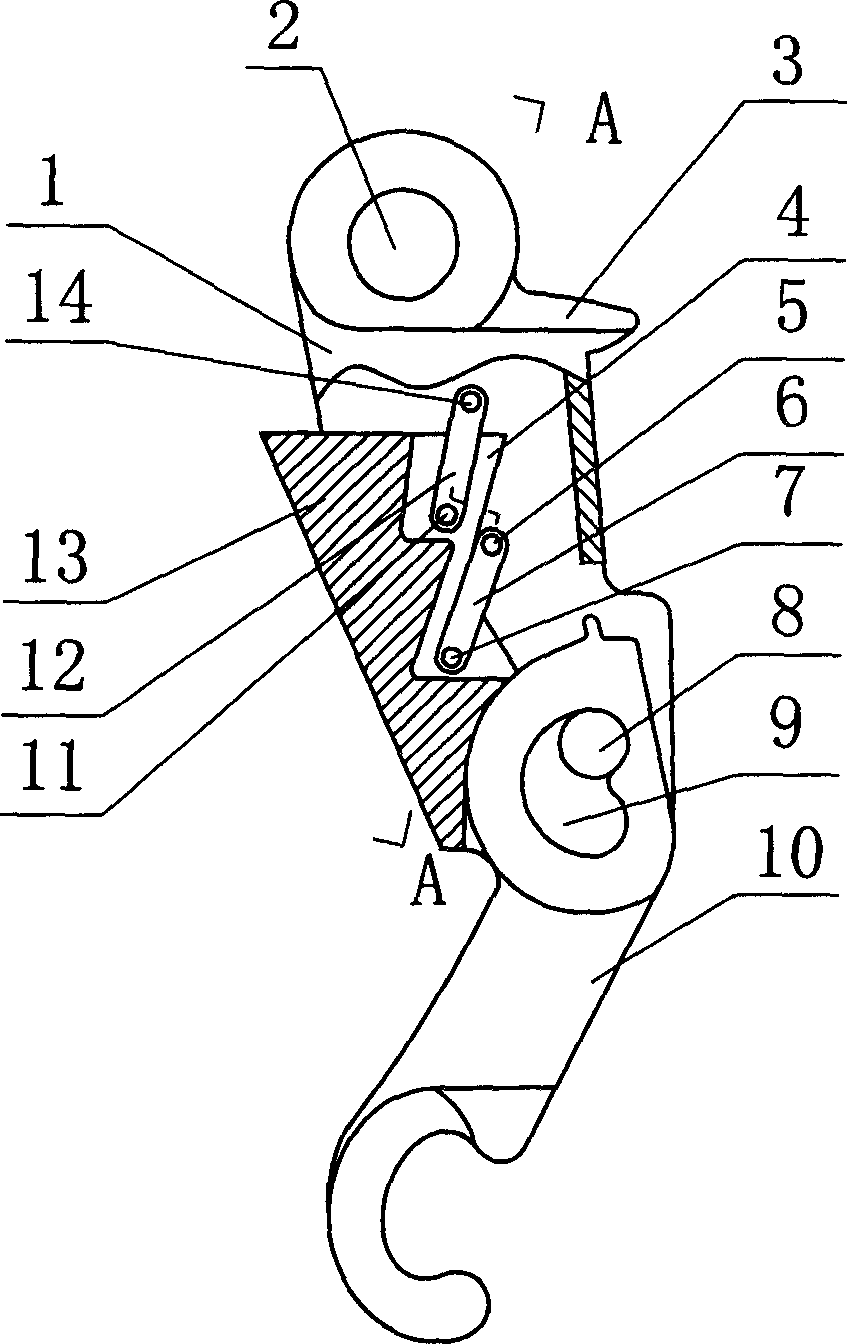
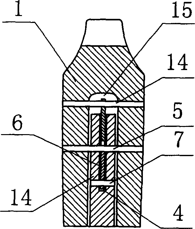
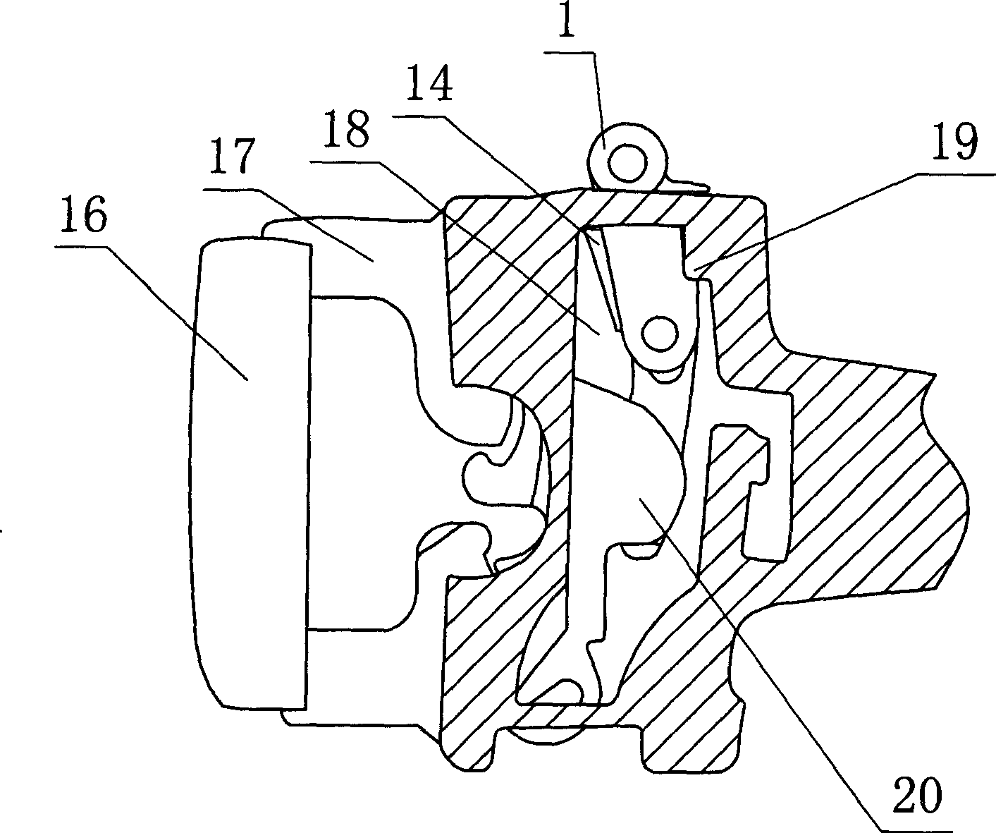
[0015] As shown in the figure, the present invention has an upper lock pin body 1, a connecting hole 2 is arranged on the top of the upper lock pin body 1, the front end surface of the upper lock pin body 1 is a slope, and the upper lock pin body 1 is provided with a The card edge 3, the lower part of the upper lock pin body 1 is provided with a mounting hole, and the upper lock pin rod 10 is installed through the pin shaft 8 in the installation hole, and the connecting hole corresponding to the upper lock pin rod 10 and the pin shaft 8 is the "heart" Shaped hole 9, through the motion between " heart " shape hole 9 and bearing pin 8, plays the positive compensation effect for the anti-jumping of vehicle coupler, realizes vehicle coupler anti-jumping. Upper lock pin body 1 is provided with chute 15, and the front end face of chute 15 is open, is connected with anti-jump iron 13 by upper and lower connecting rod 12,6 in chute 15, said anti-jump The iron 13 is provided with an in...


PUM


Abstract

The upper locking pin with hold down mechanism includes upper pin body with connecting hole, front bevel front end surface, upper clamping edge, and lower installation hole for the pin to be installed in; and upper pin rod with heart-shaped hole for connecting pin shaft. The present invention features that the upper pin body is provided with slideway and the slideway has opened front end and connected hold down iron block. The present invention has the advantages of simple structure and reliable hold down effect in preventing the automatic separation of coupler.

Description

technical field [0001] The invention belongs to coupler parts used for connecting railway vehicles, in particular to an upper lock pin provided with an anti-jump mechanism. Background technique [0002] At present, my country's railway vehicles are connected by couplers. With the implementation of railway speed-up, heavy-duty, and long-distance road operation measures, affected by operating speed, line status, locomotive traction conditions, coupler status, and vehicle loading status, coupler automatic separation failures occur from time to time during operation, especially It has been increasing in recent years. The main characteristics of coupler automatic separation faults are: most of the marshalling positions are in the middle and rear of the train, electric locomotives are mainly responsible for traction, and most of them occur at the time of speed regulation at ramps or slope change points, and there is a time limit before the speed increase. The automatic separatio...

Claims


Application Information

Patent Timeline
Patent Type & Authority Applications(China)
IPC IPC(8): B61G3/28
Inventor 张书叙
Owner 张书叙
Learn More