Display driver, electro-optical device, and method of driving electro-optical device

A display driver and electro-optical technology, applied to display drivers, in this field, can solve the problems of inability to adjust the output timing of polarity inversion signals, display quality degradation, etc., so as to avoid display quality degradation, reduce costs, and reduce chip size Effect

Inactive Publication Date: 2005-03-30
SEIKO EPSON CORP
View PDF1 Cites 6 Cited by
  • Summary
  • Abstract
  • Description
  • Claims
  • Application Information

AI Technical Summary

Problems solved by technology

However, as described above, in the circuit disclosed in (Japanese) Patent Laid-Open No. 6-38149, the output timing of the polarity inversion signal cannot be adjusted, resulting in a decrease in display quality in the mounted state.

Method used


Image

  • Display driver, electro-optical device, and method of driving electro-optical device
  • Display driver, electro-optical device, and method of driving electro-optical device
  • Display driver, electro-optical device, and method of driving electro-optical device

Examples


Embodiment Construction

[0055] Embodiments of the present invention will be described in detail below with reference to the accompanying drawings. The embodiments described below do not unduly limit the content of the invention described within the scope of the claims. In addition, not all the configurations described below are necessarily essential configuration requirements of the present invention.

[0056] 1. Display Driver

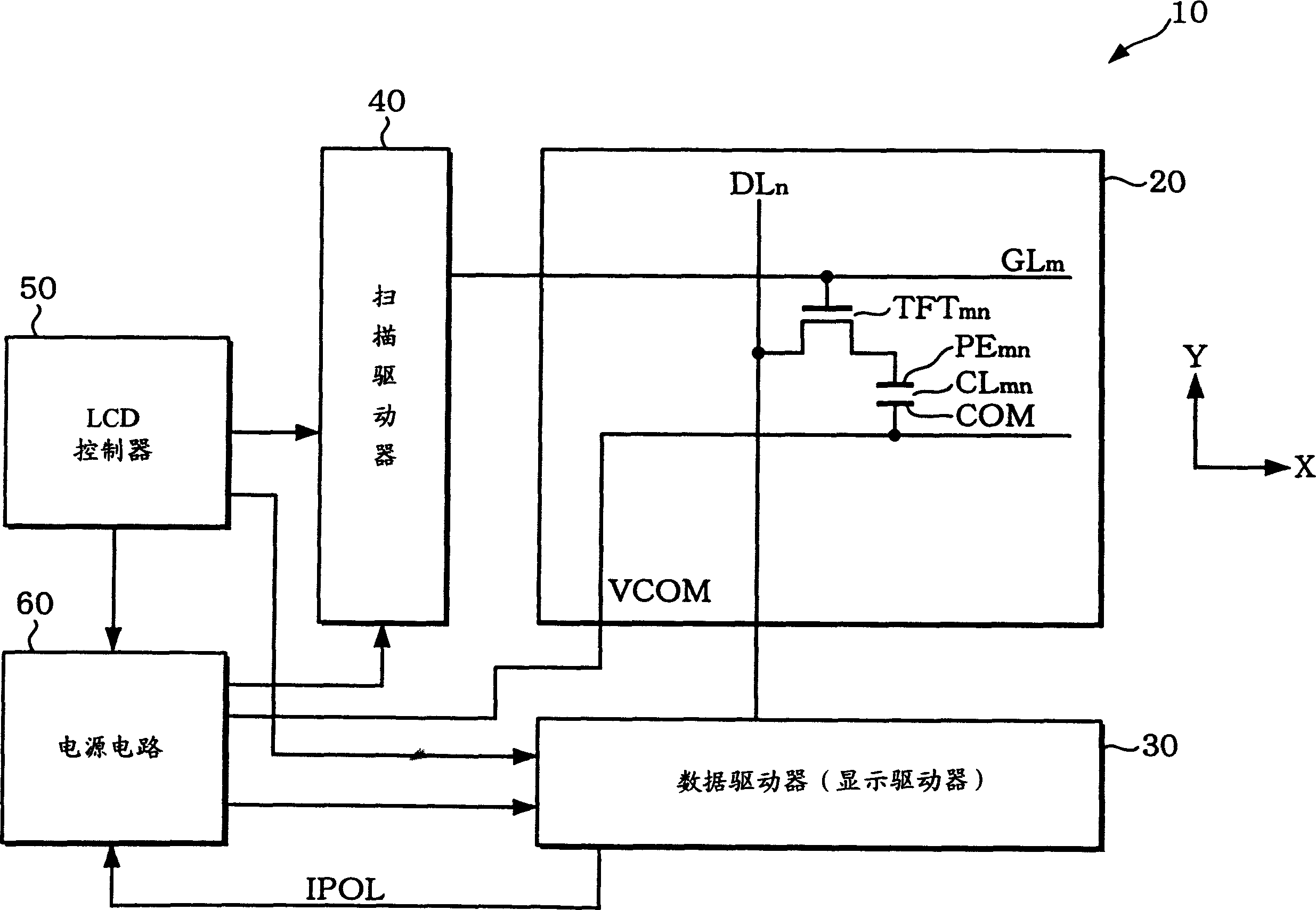
[0057] figure 1 An outline of the configuration of a liquid crystal device to which the display driver of this embodiment is applied is shown.

[0058] Liquid crystal devices (electro-optical devices in a broad sense) can be installed in mobile phones, portable information devices (PDA, etc.), digital cameras, projectors, portable audio players, mass storage devices, cameras, electronic notepads, or GPS (Global Positioning System ) and other electronic equipment.

[0059] The liquid crystal device 10 includes: a liquid crystal (LCD) display panel (in a broad sense, a dis...


PUM


Abstract

The display driver drives a data line connected through a switching element to a pixel electrode facing a counter electrode to which a voltage is supplied on the basis of polarity inversion signals holding an electrooptical material there between, and is provided with a polarity inversion signal generation circuit 110 for generating the polarity inversion signals IPOL specifying the timing of inverting the polarity of the application voltage of the electrooptical material and a driving part 120 for supplying a driving voltage corresponding to display data to the data line so as to invert the polarity of the application voltage of the electrooptical material in synchronism with the polarity inversion signal. The polarity inversion signal generation circuit generates the polarity inversion signals IPOL by delaying generated signals on the basis of horizontal synchronizing signals stipulating a horizontal scanning period and vertical synchronizing signals stipulating a vertical scanning period.

Description

Background technique [0001] The invention relates to a display driver, an electro-optical device and a driving method for the electro-optical device. [0002] In an active-matrix liquid crystal device (electro-optical device in a broad sense), writing to the liquid crystal (electro-optic material in a broad sense) layer of each pixel is performed by dot-sequential driving through a plurality of switching elements connected to one scanning line. The action of entering data. The scan lines of the liquid crystal device are sequentially selected by a scan driver, and the data lines of the liquid crystal device are driven by a data driver (display driver) according to display data. The scan driver and data driver are timing controlled by the display controller. [0003] However, display unevenness sometimes occurs due to deviations in the voltage applied to the liquid crystal. In addition, when the polarity of the voltage applied to the liquid crystal is fixed, problems such as ...

Claims


Application Information

Patent Timeline
Patent Type & Authority Applications(China)
IPC IPC(8): G02F1/133G09G3/20G09G3/36H04N5/66
CPCG09G5/006G09G3/3688G09G2310/0297G09G3/3614G09G2320/0223G09G2310/0248
Inventor 森田晶
Owner SEIKO EPSON CORP
Why Eureka
Try Eureka