
Vapor phase production of 1,1,1,2,3,3,3-heptafluoropropane from hydrogen fluoride and hexafluoropropylene

A gas-phase, fluorinated catalyst technology, applied in chemical instruments and methods, hydrogen halide addition preparation, organic chemistry, etc., can solve problems such as difficulties in HF recovery

Inactive Publication Date: 2005-03-23
THE CHEMOURS CO FC LLC
View PDF3 Cites 6 Cited by
  • Summary
  • Abstract
  • Description
  • Claims
  • Application Information

AI Technical Summary

Problems solved by technology

However, the recovery of unreacted HF is difficult due to the formation of low-boiling azeotropes of HFC-227ea and HF

Method used


Image

  • Vapor phase production of 1,1,1,2,3,3,3-heptafluoropropane from hydrogen fluoride and hexafluoropropylene

Examples


Embodiment Construction

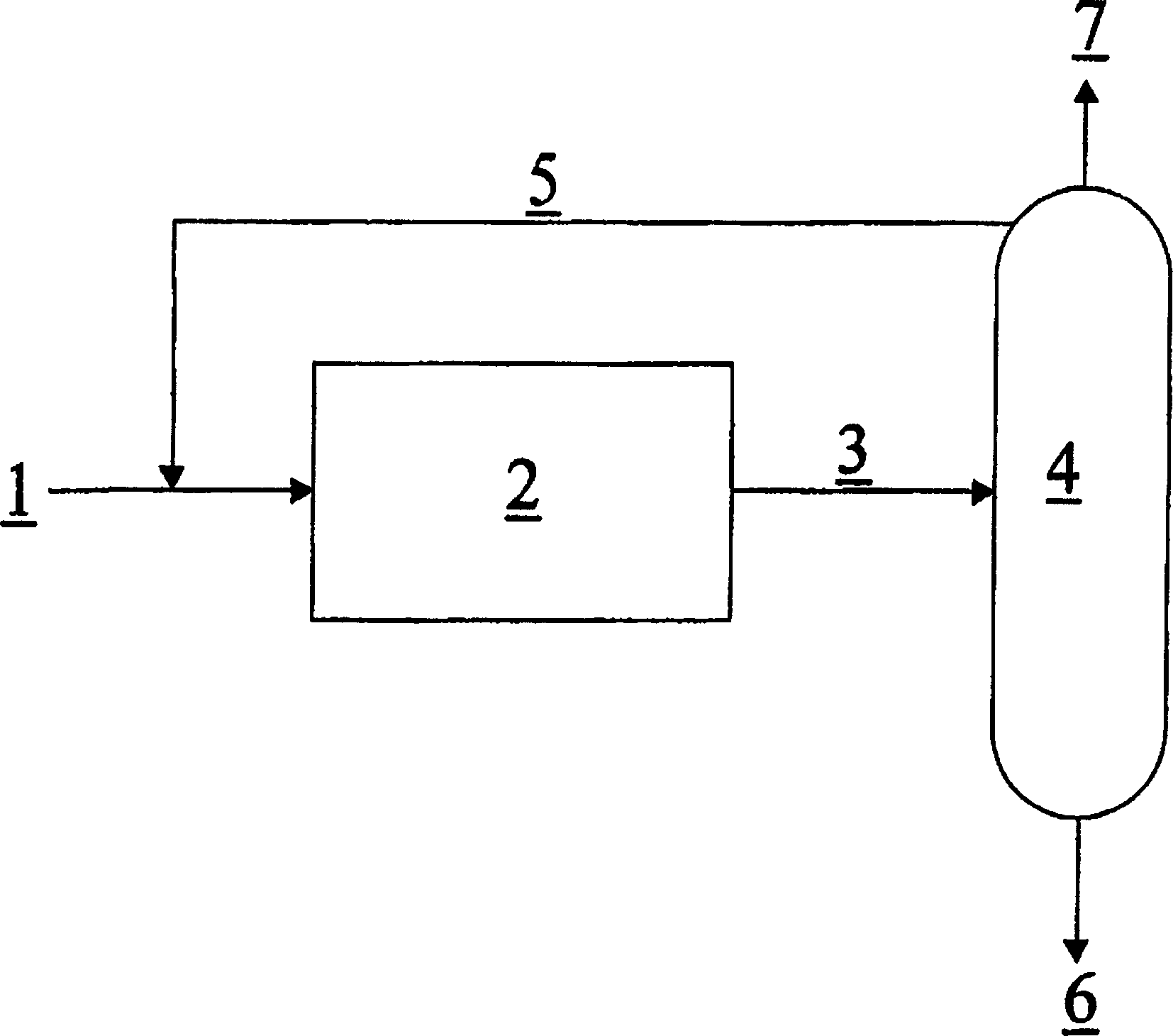
[0026] now refer to figure 1 To further illustrate the present invention, this figure is a simple schematic diagram of a device that can be used to implement the method of the present invention. exist figure 1 In, HF and HFP are vaporized, and then ( 1 ) into a gas phase catalytic reactor operating at 50 psig and 200-300°C ( 2 ). The diluent ( 5 ) into the reactor. into the reactor ( 2 ) molar ratio of HFC-227ea:HF:HFP (by 1 and 5 The mixture of streams obtained) is maintained at approximately 5:3:1 HFC-227ea:HF:HFP. reactor( 2 ) The inlet temperature is maintained at 200°C. By adjusting the diluent flow ( 5 ) flow rate, the entire reactor ( 2 ) was controlled and a high conversion of HFP (95%) was obtained. The reaction mixture containing HF and HFC-227ea was condensed, and ( 3 ) into a distillation column operating at 50-150 psig ( 4 ). HF and HFC-227ea form a low-boiling azeotrope, and substantially all of the HF and the azeotropic amount (or more) of HFC-...


PUM

PropertyMeasurementUnit
boiling pointaaaaaaaaaa

Abstract

A process for the production of HFC-227ea from HF and HFP is provided. This process takes advantage of an azeotropic composition of HF and HFC-227ea in order to produce HFC-227ea essentially free of HF and recycle unreacted HF back to the reactor. The recycle of said azeotropic composition, also allows the use of HFC-227ea as a diluent to aid in control of reactor temperature for a highly exothermic reaction.

Description

[0001] Cross-reference to related applications [0002] This application claims priority to US Provisional Application 60 / 339,923, filed October 31,2001. field of invention [0003] The present invention relates to a chemical production process for the preparation of 1,1,1,2,3,3,3-heptafluoropropane (HFC-227ea) from hydrogen fluoride (HF) and hexafluoropropylene (HFP). Background technique [0004] Hydrocarbons containing chlorine or bromine, especially chlorofluorocarbons or bromofluorocarbons, have been widely used as solvents, blowing agents, refrigerants, cleaning agents, aerosol propellants, heat transfer media, dielectrics, fire extinguishing agents, and power Circulate the working fluid. Many of these chlorofluorocarbons and bromofluorocarbons are considered harmful to the Earth's ozone layer. Worldwide efforts to develop feedstocks with lower ozone depletion potential have identified a number of hydrofluorocarbons (i.e., compounds containing only carbon, hydrogen a...

Claims


Application Information

Patent Timeline
Patent Type & Authority Applications(China)
IPC IPC(8): C07C17/087C07C17/38C07C17/383
CPCC07C17/38C07C17/087C07C17/383C07C19/08
Inventor R·N·米勒M·J·纳帕D·J·托顿
Owner THE CHEMOURS CO FC LLC
Learn More