
Compound jet tower disk

A technology of tray and jet cover, applied in the field of composite jet tray, can solve problems such as difficulty in adapting to operating conditions, and achieve the effects of stable operation and high operating flexibility

Inactive Publication Date: 2005-03-23
HEBEI UNIV OF TECH
View PDF0 Cites 7 Cited by
  • Summary
  • Abstract
  • Description
  • Claims
  • Application Information

AI Technical Summary

Problems solved by technology

Although these trays have the advantage of large operating flexibility, it is difficult to adapt to the operating conditions of a large gas-liquid load in the tower. Therefore, it is of great practical significance and certainty to develop a spray tray suitable for a large gas-liquid load in the tower. economic benefits

Method used


Image

  • Compound jet tower disk
  • Compound jet tower disk

Examples


Embodiment Construction

[0014] Embodiment of the present invention will be further described below in conjunction with accompanying drawing:

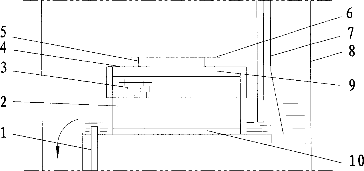
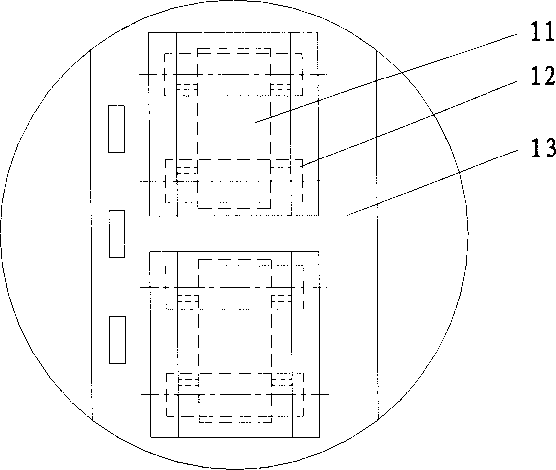
[0015] The working principle of the compound injection tray is: the liquid flows down from the overflow device and the auxiliary downcomer of the upper tray, and the gas enters the injection hood from the bottom of the tray through the air hole, and the gas enters the injection hood and rises at the same time , the liquid enters the spray hood through the bottom gap of the spray hood, and is blown into a thin liquid film by the gas. When the liquid film is lifted by the gas, it is broken into droplets under the action of surface tension. The gas-liquid mixed flow is ejected from the ejection hole and the ejection channel. Part of the gas-liquid mixed flow ejected from the top is sprayed on the gas-liquid separation plate of the lower layer, and the rest will be sprayed onto the gas-liquid separation plate of the upper layer through the air-lift holes on the lo...


PUM


Abstract

A combined tower tray is composed of tower plate with regularly arranged gas-raising holes, spray unit on said tower plate, liquid collector, down-flow spout and secondary down-flow spout. Said spray unit has a spray cover above said tower plate and with spray holes, and two-layer gas-liquid separating unit above said spray cover and consisting of a perforated plate and a blind plate.

Description

technical field [0001] The invention relates to a compound injection tray, which belongs to the structure technology of the internal parts of the tower used for mass transfer and heat transfer in the operation processes of chemical distillation, absorption and desorption. Background technique [0002] The structure of the existing injection trays used for rectification towers, absorption towers, and desorption towers includes trays, injection units on the trays, liquid receiving tanks, downcomers and auxiliary downcomers. The injection unit is: a directional injection hole opened on the tray, such as a solid tongue tray, or an injection element arranged on the tray, such as a new vertical sieve tray. Although these trays have the advantage of large operating flexibility, it is difficult to adapt to the operating conditions of larger gas-liquid loads in the tower. Therefore, it is of great practical significance and certainty to develop a spray tray suitable for larger gas-li...

Claims


Application Information

Patent Timeline
IPC IPC(8): B01D3/18
Inventor 李春利李柏春吕建华刘继东
Owner HEBEI UNIV OF TECH
Learn More