Ultrasonic probe and method for fabricating the probe

A manufacturing method and ultrasonic technology, applied in ultrasonic/sonic/infrasonic diagnosis, sonic diagnosis, infrasonic diagnosis, etc., can solve problems such as cracking of piezoelectric materials under processing stress

Inactive Publication Date: 2005-03-23
KK TOSHIBA +1
View PDF1 Cites 10 Cited by
  • Summary
  • Abstract
  • Description
  • Claims
  • Application Information

AI Technical Summary

Problems solved by technology

[0012] However, if the end of the piezoelectric vibrator protrudes from the end surface of the spacer, and the protruding part has a structure suspended in the air, the processing stress generated during the slicing process is likely to cause the problem of cracking of the piezoelectric material.

Method used


Image

  • Ultrasonic probe and method for fabricating the probe
  • Ultrasonic probe and method for fabricating the probe
  • Ultrasonic probe and method for fabricating the probe

Examples


Embodiment Construction

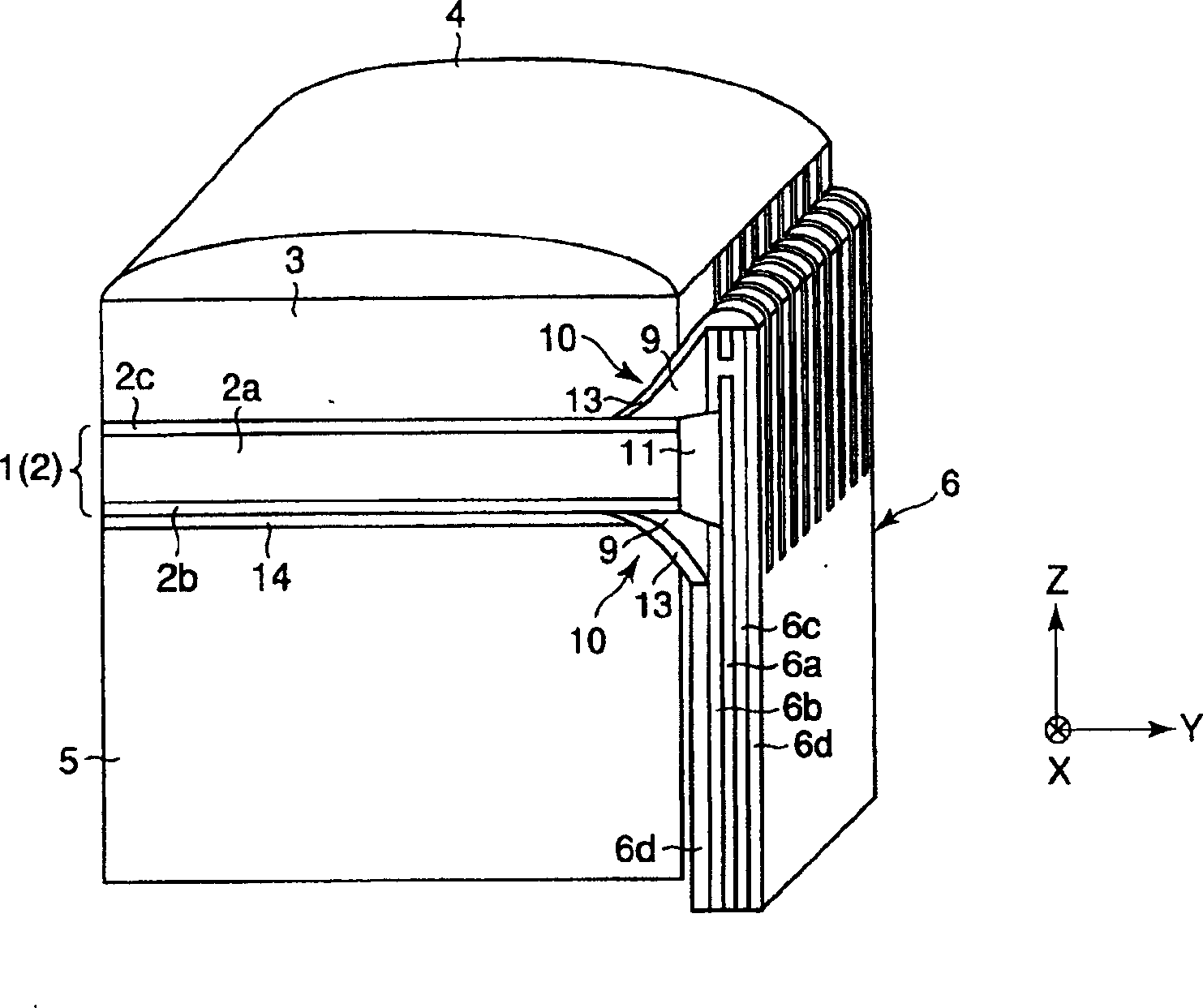
[0033] Refer to the following Figure 1 to Figure 8 A first aspect of the present invention will be described. figure 1 It is a perspective view showing the structure of the ultrasonic probe as the first embodiment of the present invention. figure 2 It is a sectional view showing the structure of the ultrasonic probe in the same embodiment as above. image 3 for display from figure 2 A cross-sectional view obtained by cutting the structure of the ultrasonic probe in the same embodiment as above along line A-A. Figure 4 for display from figure 2 A cross-sectional view obtained by cutting along line B-B.

[0034] figure 1 with figure 2 The ultrasonic probe shown in has a piezoelectric vibrator 1 . The piezoelectric vibrator 1 is made in the shape of a cuboid, and its three edges are perpendicular to each other, and correspond to the three directions of x, y, and z respectively.

[0035] Such as image 3 As shown, the piezoelectric vibrator 1 is composed of a plur...


PUM

PropertyMeasurementUnit
Bending angleaaaaaaaaaa

Abstract

An ultrasonic probe comprises a piezoelectric transducer(1) for transmitting / receiving ultrasonic waves; and a conductive substrate(6) electrically connected to the piezoelectric transducer. The conductive substrate is opposed to a side surface of the piezoelectric transducer. A corner portion(10) formed by the piezoelectric transducer and the conductive substrate is provided with a conductive material for electrically connecting the piezoelectric transducer and the conductive substrate.

Description

[0001] Cross References to Related Applications [0002] This application is based on and claims priority from prior Japanese Patent Application No. 2003-46515 filed on February 24, 2003, the entire contents of which are hereby incorporated by reference. technical field [0003] The present invention relates to an ultrasonic probe for receiving and transmitting ultrasonic waves and a manufacturing method thereof. Background technique [0004] For example, ultrasonic diagnostic devices are used in medical diagnosis and industrial diagnosis, which detect internal lesions and cracks in pipes by emitting ultrasonic waves to diagnostic objects such as human bodies and pipes and receiving reflected waves. This ultrasonic diagnostic device is composed of the ultrasonic diagnostic device itself and an ultrasonic probe for emitting and receiving ultrasonic waves. [0005] Figure 14 with Figure 15 The configuration of an ultrasonic probe of a conventional medical ultrasonic diagno...

Claims


Application Information

Patent Timeline
Patent Type & Authority Applications(China)
IPC IPC(8): G01N29/24A61B8/00B06B1/06H04R17/00
CPCA61B8/00B06B1/0622B63B25/08B63J2/10F16K31/20F24F13/12Y02T70/00
Inventor 须藤正昭比企进佐藤信一佐藤太平
Owner KK TOSHIBA
Why Eureka
Try Eureka