
Small size antenna, surface mounting type antenna and antenna device as well as radio communication device

一种表面安装型、小型天线的技术,应用在天线装置,无线通信装置,小型表面安装型天线领域,能够解决难安装基板表面安装、无法取得天线特性、天线尺寸增大等问题,达到良好天线特性、削减缺口不良率、波长缩短的效果

Inactive Publication Date: 2005-03-16
KYOCERA CORP
View PDF2 Cites 6 Cited by
  • Summary
  • Abstract
  • Description
  • Claims
  • Application Information

AI Technical Summary

Problems solved by technology

[0019] However, in Figure 13 In the conventional surface mount antenna 81 shown, it is necessary to adjust the helical radiation in order to match the operating frequency of the surface mount antenna 81 with respect to the low frequency f1 and the high frequency f2 of the wireless signal used in the communication system. The length and spacing of the electrodes 82, 83, the adjustment is very laborious
[0020] In addition, when attempting to increase the specific permittivity of the substrate 86 and miniaturize the surface mount antenna, an unexpected and unnecessary resonance mode occurs between the spirally long radiation electrodes 82, 83 and the ground conductor 93, making it impossible to achieve stable There is a problem that it is difficult to miniaturize because of the characteristics of the antenna that can correspond to dual frequency
[0021] In addition, in the antenna for a mobile communication terminal described in JP-A-2002-204120, there is a problem that it is difficult to surface-mount the mounting substrate.
[0022] In the antenna device described in Japanese Unexamined Patent Publication No. 2002-314330, since the radiation electrode is a planar pattern, the size of the antenna increases, and there is a problem that miniaturization is difficult

Method used


Image

  • Small size antenna, surface mounting type antenna and antenna device as well as radio communication device
  • Small size antenna, surface mounting type antenna and antenna device as well as radio communication device
  • Small size antenna, surface mounting type antenna and antenna device as well as radio communication device

Examples


Embodiment

[0192] Next, Embodiment 1 related to Embodiment 1 of the present invention will be described.

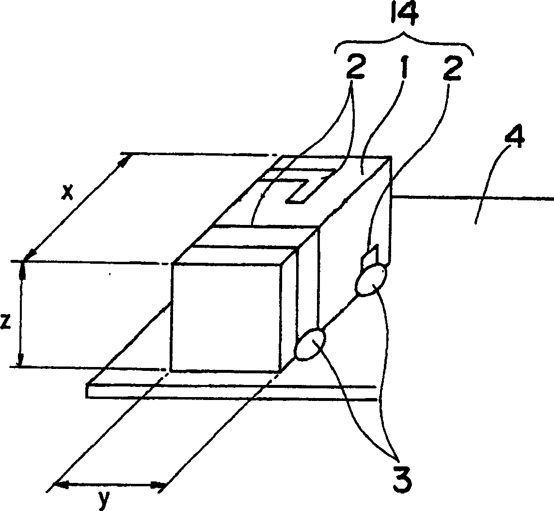
[0193] In this example, making figure 1 A small antenna 14 is shown.

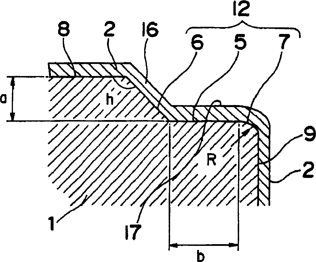
[0194] First, using alumina ceramics (specific permittivity: 9 to 10), a cuboid-shaped substrate 1 with an external dimension x of 10 mm, an external dimension y of 4 mm, and a thickness z of 4 mm was produced. It should be noted that for the width b of the flat portion 5 of the stepped portion 12, the depth a of the stepped portion, the radius of curvature R of the boundary portion 7, and the angle h of the inclined portion 6, the size of the metal mold and the barreling time were changed, and Table 1 was made. Samples of various sizes shown.

[0195] Then, Ag thick films were printed on the four sides of the substrate 1, dried in the air at a predetermined temperature, and sintered to form a conductor 2 with a thickness of 0.02 mm. Here, the size of the conductor 2 is determined so that the operating freque...


PUM


Abstract

In order to provide a small size antenna where excellent antenna properties can be stably gained, a frequency adjustment is easy and a simple measurement is possible, according to the present invention, a small size antenna formed of a conductor of at least two adjoining surfaces of a base in rectangular parallelepiped form made of dielectric ceramics is characterized in that: a step is made of a flat portion parallel to one surface of the two adjoining surfaces and an inclining portion located between the one surface and the flat portion, in a corner portion of the two surfaces on which the conductor is formed; the width of the flat portion is 0.08 mm or less; and a border portion between the flat portion and the other surface of the two adjoining surfaces is a curve having a curvature radius R of 0.03 mm to 0.2 mm.

Description

technical field [0001] The present invention relates to the field of communication, in particular to a small surface-mounted antenna built into a mobile communication device such as a mobile phone, in particular to a small surface-mounted antenna capable of supporting dual frequencies, an antenna device and a wireless communication device using them. Background technique [0002] In recent years, mobile communication devices such as mobile phones have made great progress in miniaturization. Along with the miniaturization of such communication equipment, miniaturization of the antenna built in the communication equipment is also required, and small antennas with conductors formed on the surface of a rectangular parallelepiped substrate and surface-mounted on the internal circuit board of the communication equipment are being put into practical use. [0003] 4 is a perspective view schematically showing a conventional small antenna, Figure 5 It is a longitudinal sectional vie...

Claims


Application Information

Patent Timeline
Patent Type & Authority Applications(China)
IPC IPC(8): H01Q1/22H01Q1/24H01Q1/36H01Q1/38H01Q5/10H01Q5/371H01Q9/04H01Q9/40H01Q13/08H01Q21/30
CPCH01Q1/243H01Q1/2283H01Q1/38H01Q5/364H01Q21/30H01Q5/0055H01Q13/08H01Q1/24
Inventor 古野刚和多田一雄滨田浩儿村川俊一
Owner KYOCERA CORP
Learn More