
Condensed water discharge device of dehumidifier

A discharge device and condensed water technology, applied in the direction of preventing condensed water, etc., to achieve the effect of easy assembly, avoiding water leakage, and easy assembly

Inactive Publication Date: 2005-03-09
LG ELECTRONICS (TIANJIN) APPLIANCES CO LTD
View PDF0 Cites 1 Cited by
  • Summary
  • Abstract
  • Description
  • Claims
  • Application Information

AI Technical Summary

Problems solved by technology

[0006] However, in order to pour out the condensed water in the water tank of the conventional dehumidifier, the water tank must be pulled out from the dehumidifier

Method used


Image

  • Condensed water discharge device of dehumidifier
  • Condensed water discharge device of dehumidifier
  • Condensed water discharge device of dehumidifier

Examples


Embodiment Construction

[0024] The present invention will be described in detail below with reference to the accompanying drawings and embodiments.

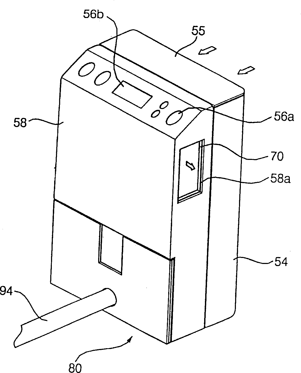
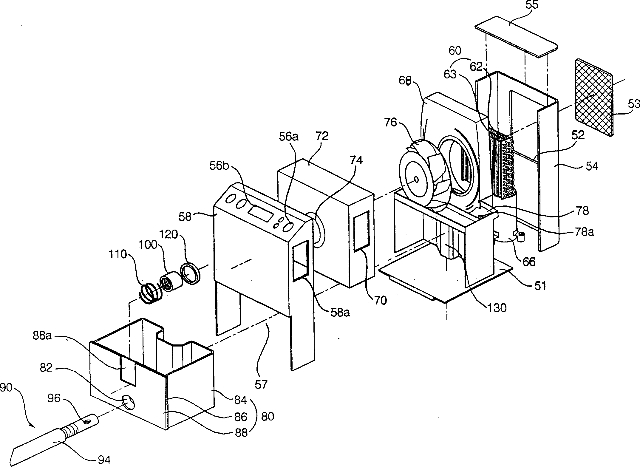
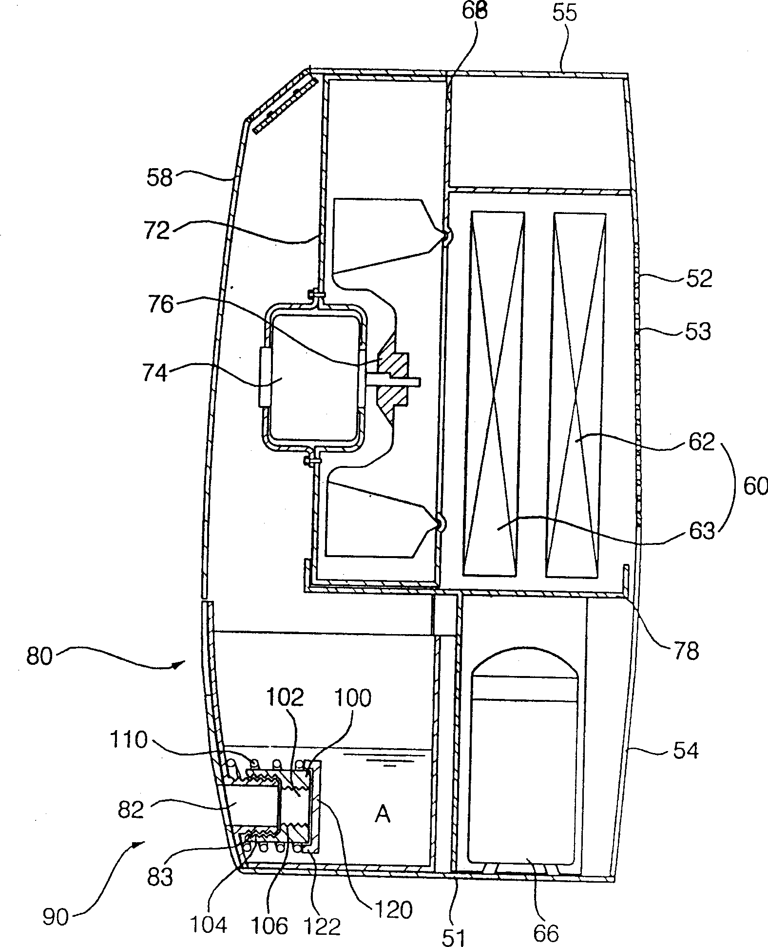
[0025] figure 1 It is the appearance structural diagram of installing the drainage rubber pipe in the tank of the dehumidifier according to the present invention; figure 2 It is an exploded structure diagram of the dehumidifier of the present invention; image 3 It is an internal structure diagram when no drainage rubber pipe is installed in the water tank of the present invention; Figure 4 It is an internal structure diagram when a drainage rubber pipe is installed in the water tank of the present invention.

[0026] Such as Figure 1 to Figure 4 As shown, the dehumidifier according to this embodiment includes: a chassis (51); and a casing (54) that is located on the upper side of the chassis (51), the suction hole (52) is formed on the back, and the top, bottom and front are open; and The top cover (55) that is positioned on the upper side of th...


PUM


Abstract

A condensed water discharging mechanism for demoistener is composed of a condensed water collector with a insertion port, a water discharging rubber tube whose one end is inserted in said insertion port, a nut for fastening the rubber tube, a spring fixed to said water collector, and a plug fixed to another end of said spring for closing the discharging port when said rubber tube is pulled out.

Description

technical field [0001] The invention relates to a device for collecting or removing condensed water, in particular to a condensed water drainage device for a dehumidifier that can simply and easily discharge the condensed water stored in a water tank. Background technique [0002] A general dehumidifier first sucks the humid air in the room into the casing, makes it pass through a heat exchanger composed of a condenser and an evaporator in which the refrigerant flows, thereby reducing the humidity, and then discharges the dehumidified air into the room , A device that reduces indoor humidity. [0003] The dehumidifier uses the method of evaporating the liquid refrigerant in the evaporator and absorbing heat from the surrounding air. The evaporation of the refrigerant can lead to a decrease in the temperature of the evaporator, and the temperature of the air passing through the evaporator will also decrease at this time. [0004] As the temperature around the evaporator drop...

Claims


Application Information

Patent Timeline
Patent Type & Authority Applications(China)
IPC IPC(8): F24F13/22
Inventor 裴京善白镇哲李宗赫杨成龙
Owner LG ELECTRONICS (TIANJIN) APPLIANCES CO LTD
Learn More