
Method of lowering residual fluorind in sedimentation reaction chamber cavity body

A technology of deposition reaction and chamber, applied in gaseous chemical plating, metal material coating process, coating, etc., can solve problems such as process pollution, gate line short circuit, fluorine ion residue, etc.

Inactive Publication Date: 2005-03-09
TPO DISPLAY
View PDF0 Cites 3 Cited by
  • Summary
  • Abstract
  • Description
  • Claims
  • Application Information

AI Technical Summary

Problems solved by technology

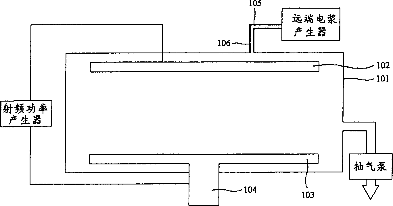
[0012] Because at present, a radio frequency power generator is used to dissociate hydrogen as a reaction gas to form a hydrogen ion plasma, which is filled in the deposition reaction chamber cavity 101, so that the hydrogen ion plasma is fully combined with the fluorine ion to reduce the residual fluoride ion In the cavity, however, the remote plasma generator is used to form a plasma from the fluorine-containing gas used as the cleaning gas, and the plasma is introduced into the deposition reaction chamber cavity 101 through the hollow pipeline 105 to use high-efficiency plasma to clean the deposition In the steps of the reaction chamber cavity 101, fluoride ions also exist on the surface of the pipeline in the hollow pipeline 105, but they cannot be removed by the hydrogen ion plasma formed by the radio frequency power generator, resulting in residual fluoride ions in the hollow pipeline 105 In this way, it will pollute the subsequent process. In addition to affecting the process conditions and reducing the process stability, it may also drop from the deposition reaction chamber on the substrate and cause irreparable defects, such as gate line short circuit

Method used


Image

  • Method of lowering residual fluorind in sedimentation reaction chamber cavity body
  • Method of lowering residual fluorind in sedimentation reaction chamber cavity body
  • Method of lowering residual fluorind in sedimentation reaction chamber cavity body

Examples


Embodiment Construction

[0027] In order to make the above and other purposes, features, and advantages of the present invention more clearly understood, the preferred embodiments are specifically cited below, together with the accompanying drawings, and are described in detail as follows:

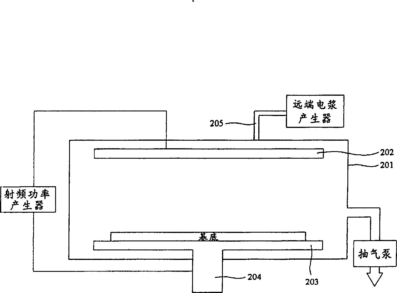
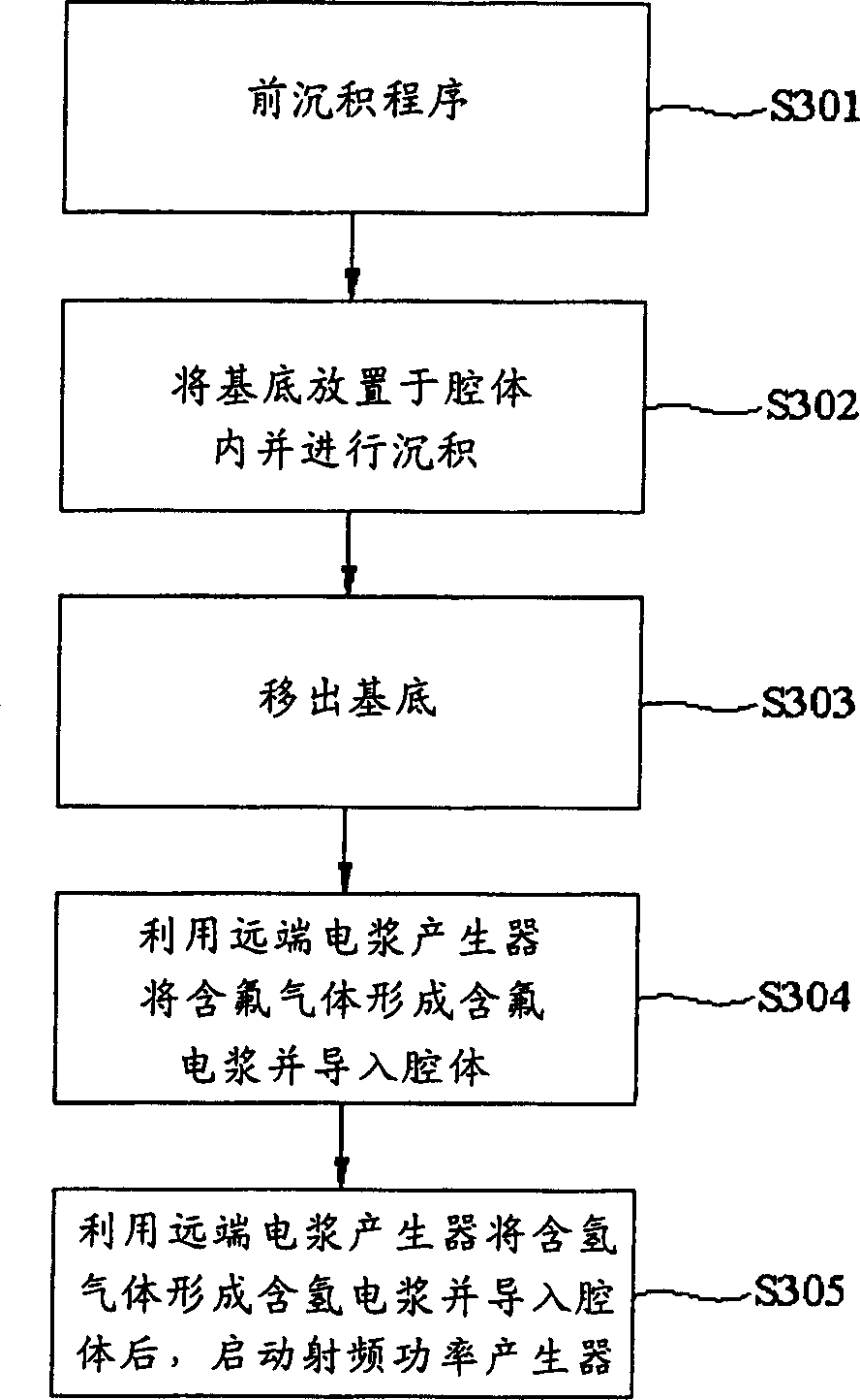
[0028] Please also refer to figure 2 and image 3 , figure 2 is a deposition reaction device showing the present invention; image 3 It is a flow chart showing the method for reducing fluorine residue in the chamber of the deposition reaction chamber provided by the present invention.

[0029] The deposition reaction device includes a deposition reaction chamber cavity 201 , a radio frequency (RF) power generator, a remote plasma generator, and an air pump. The chamber body 201 of the deposition reaction chamber has an upper electrode 202 , a lower electrode 203 , and a support frame 204 , and the lower electrode 203 is placed on the support frame 204 . The upper electrode 202 and the lower electrode 203 are...


PUM


Abstract

A process for decreasing the residual fluorine in depositing reaction cavity includes such steps as providing a depositing reactor which is composed of depositing reaction cavity, far-end plasma generator and RF power generator, introducing F-contained gas to said plasma generator for generating F-contained plasma, guiding it into depositing reaction cavity, introducing H2-contained gas to said plasma generator for generating hydrogen-contained plasma guiding it into depositing reaction cavity, and turning on RF power generator.

Description

[0001] The technical field to which the invention belongs [0002] The invention relates to a method for cleaning residues in a deposition reaction chamber, in particular to a method for using a radio frequency power generator and a remote plasma generator to generate hydrogen-containing Gas plasma to remove residual fluoride ions. Background technique [0003] In the step of forming the structural layer on the substrate, chemical vapor deposition (chemical vapor deposition, CVD) is a method that is often used. After the substrate is subjected to a deposition reaction, the structural layer will be formed on the surface of the substrate, and the deposition The speed will increase with the temperature in the deposition reaction chamber, and the thickness of the structure will increase with the deposition time. However, since the temperature of the chamber surface of the deposition chamber increases with the temperature in the deposition chamber, a structure layer is also deposi...

Claims


Application Information

Patent Timeline
IPC IPC(8): C23C16/00
Inventor 林辉巨
Owner TPO DISPLAY
Learn More