
Artificial source time frequency electro magnetic bathymetry

A time-frequency, electromagnetic sounding technology, applied in the field of electromagnetic sounding exploration, can solve problems such as difficult to solve geological problems, single physical parameters, and only one vertical magnetic field.

Inactive Publication Date: 2005-02-16
BC P INC CHINA NAT PETROLEUM CORP +1
View PDF0 Cites 28 Cited by
  • Summary
  • Abstract
  • Description
  • Claims
  • Application Information

AI Technical Summary

Problems solved by technology

In addition, the measurement parameters of existing methods are limited to one electric field and one magnetic field component, such as the CSAMT method; or only one vertical magnetic field is measured, such as the LOTEM method
The physical parameters studied are single, limited to resistivity parameters
Therefore, there is a gap between these methods and the actual requirements in terms of ability and accuracy to solve geological problems, and the method itself is difficult to solve the existing geological problems perfectly!

Method used


Image

  • Artificial source time frequency electro magnetic bathymetry
  • Artificial source time frequency electro magnetic bathymetry
  • Artificial source time frequency electro magnetic bathymetry

Examples


Embodiment 1

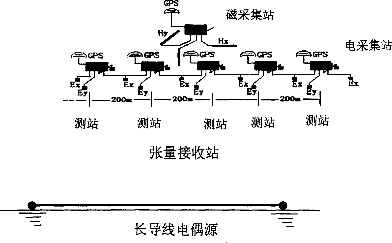
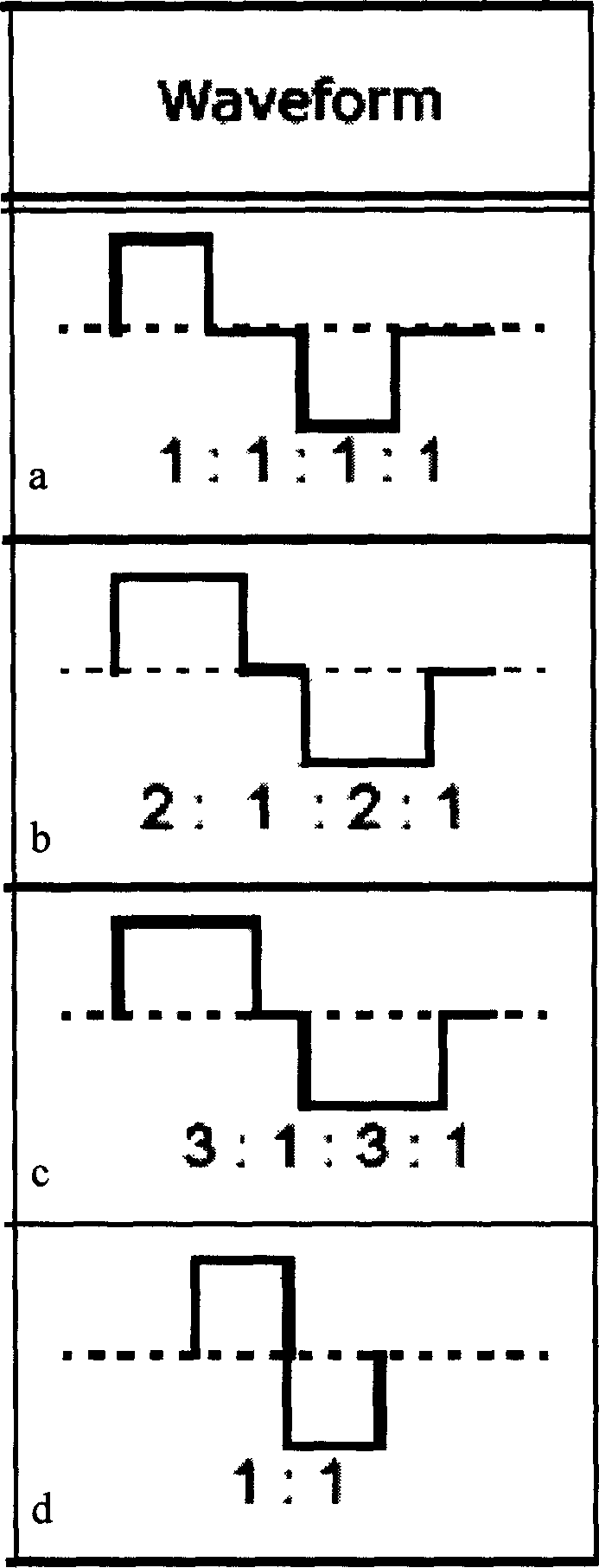
[0013] Embodiment 1 (FIG. 1): long wire galvanic source is excited, and an electromagnetic field receiving station is arranged at a certain distance from the galvanic source, and a 5-component tensor measuring station is used. The measurement direction of the horizontal component of the electromagnetic field at the receiving station is parallel and perpendicular to the long wire galvanic source. The excitation waveform is a positive and negative square wave with a duty ratio of 1:1 (Figure 3d), the highest frequency of the transmitted signal is 256 Hz, and the low frequency is 1024 seconds. Continuous excitation from low frequency to high frequency. Each frequency of the low-frequency band was repeatedly excited 3 times, and each frequency of the high-frequency band was repeatedly excited 1024 times, and the interval was gradually increased (see Table 1). The signals of each frequency of each field component are superimposed indoors to obtain 5-component signals of the electr...

Embodiment 2

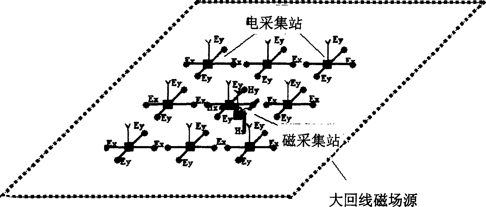
[0014] Embodiment 2 (Fig. 2): The large loop magnetic field source is excited, and the electromagnetic field receiving station is arranged in the large loop source, and a 5-component tensor measuring station is used. The measurement direction of the horizontal component of the electromagnetic field at the receiving station is parallel or perpendicular to the large loop magnetic field source. The excitation waveform is a positive and negative square wave with a duty ratio of 1:1:1:1 (Figure 3a), the highest frequency of the transmitted signal is 256Hz, and the low frequency is 1024 seconds. Continuous excitation from low frequency to high frequency (see Table 1), repeated excitation 3 times for each frequency in the low frequency band, and 1024 repetitions for each frequency in the high frequency band, gradually increasing. The signals of each frequency of each field component are superimposed indoors to obtain 5-component signals of the electromagnetic field: Ex, Ey, Hx, Hy an...


PUM


Abstract

The present invention can implement the utilization of electromagnetic depth-measuring exploration method in frequency-domain method and time-domain method. Said invention utilizes that exciting and receiving a series of frequency (period) pulses to research the law of whole spectrum, at the same time, research the signal attenuation law of every frequency (period), from short period to long period, the reflected underground informations can be progressively deepened, the superposition of these informations can raise exploration accuracy, and the time-domain and frequency-domain boty can be used for making mutual check by means of time-frequency conversion so as to greatly raise exploration accuracy. Said invention can be mainly used for making exploration of oil, gas, mineral resources and geothermal resource.

Description

[0001] Involved areas [0002] The invention relates to geophysical exploration, which is an electromagnetic sounding exploration method. Background technique [0003] At present, in the exploration of oil and gas, minerals and geothermal resources, the artificial source electromagnetic method is widely used. But the existing methods are frequency domain or time domain methods. That is to say, it is to stimulate the measurement of one frequency point by one frequency point, such as the controlled source acoustic frequency magnetotelluric method (CSAMT); or to stimulate a pulse (square wave) to measure its decay curve with time after power off, such as long offset instantaneous Variable Electromagnetic Method (LOTEM). In addition, the measurement parameters of existing methods are limited to one electric field and one magnetic field component, such as the CSAMT method; or only one vertical magnetic field is measured, such as the LOTEM method. The physical parameters studied ...

Claims


Application Information

Patent Timeline
IPC IPC(8): G01V3/08
Inventor 何展翔
Owner BC P INC CHINA NAT PETROLEUM CORP
Learn More