
Magnetron

A magnetron and inductor technology, applied in the field of magnetron, can solve the problems of insulation failure, high frequency absorption element 2 cracks, noise attenuation, etc.

Inactive Publication Date: 2005-02-09
PANASONIC CORP
View PDF1 Cites 10 Cited by
  • Summary
  • Abstract
  • Description
  • Claims
  • Application Information

AI Technical Summary

Problems solved by technology

This structure is successful in solving the following problems: one is the problem of insulation failure due to burning of the insulating film coated on the winding of the choke coil 5, and the other is the problem of cracks in the high-frequency absorbing element 2 ( See, for example, JP-B-57-017344 )
[0004] However, even if the number of turns of the winding in the iron-core inductor 3 is adjusted, the conventional magnetron can only attenuate the noise at a frequency of 400 MHz or lower, and even if the number of turns of the winding in the air-core inductor 4 is adjusted Adjustment, the conventional magnetron can only attenuate the noise in the range of 700 to 1000MHz
Therefore, there is a problem that noise in the range from 500 to 700MHz will interfere with radio waves for communication

Method used


Image

  • Magnetron
  • Magnetron
  • Magnetron

Examples


Embodiment Construction

[0027] Preferred embodiments of the present invention will be described below with reference to the accompanying drawings.

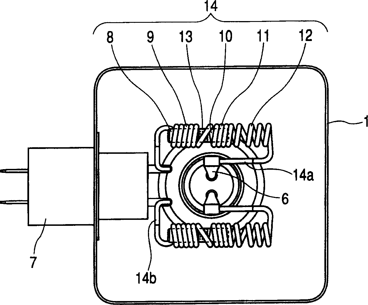
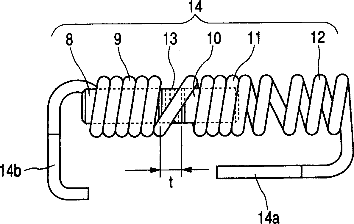
[0028] figure 1 is a plan view schematically showing the arrangement of the LC filter circuit in the magnetron according to the first embodiment of the present invention. Figure 2A is a front view showing key components of the choke coil in the magnetron according to the first embodiment of the present invention. image 3 is a graph showing the amount of noise attenuation at the frequency bands of 700 MHz and 500 MHz with respect to the change in the size of the gap between the first and second core inductors in the choke coil in the magnetron of the present invention situation. Figure 4 is a graph showing how the amount of noise attenuation changes with respect to frequencies from 30 MHz to 1 GHz when the magnetron according to the first embodiment is installed in a microwave oven. Throughout the drawings to be referred to later, for the sake of s...


PUM

PropertyMeasurementUnit
sizeaaaaaaaaaa
widthaaaaaaaaaa

Abstract

A magnetron that includes a choke coil which is connected at one end to a cathode terminal and at the other end to a capacitor to form an LC circuit. The choke coil is made up of a first core type inductor, a second core type inductor and an air-core inductor, connected to the cathode terminal, all of which are connected in series and where the first and second core type inductors are separated by a 1 mm to 6 mm gap. The first and second core type inductors have a bar like, high-frequency absorbing member located within their respective windings.

Description

technical field [0001] The present invention relates to a magnetron used in a high-frequency heating device such as a microwave oven. Background technique [0002] Such as Figure 5 As shown in , in a conventional magnetron, a filter housing 1 includes a choke coil 5 , a cathode input line 6 and a capacitor 7 . The choke coil 5 is made with an iron-core inductor 3 and an air-core inductor 4, which are connected in series. The iron-core inductor 3 has a high-frequency absorbing element 2 formed of a rod-shaped ferrite in its winding. The air-core inductor 4 has no high-frequency absorbing elements in its winding. The cathode input line 6 is connected to the first end 5 a of the choke coil 5 , which is relatively close to the air-core inductor 4 . The capacitor 7 has a capacitor terminal connected to the second end 5 b of the choke 5 , said second end 5 b being relatively close to the core inductor 3 . [0003] In this magnetron, the air-core inductor 4 in the choke 5 is i...

Claims


Application Information

Patent Timeline
Patent Type & Authority Applications(China)
IPC IPC(8): H01F3/10H01F17/04H01F37/00H01J23/15H01J23/54H01J25/50
CPCH01F2038/003H01F17/045H01J25/50H01F37/00H01J23/15H01F3/10
Inventor 落合宏宫本和彦菅野浩
Owner PANASONIC CORP
Learn More