


Quick Research
Generate reliable direction feasibility study reports for your R&D in just a few steps.

Technical Q&A
Discover and master advanced knowledge NOW. Basics, ideas, possibilities, all at once.

Find Solutions
As an expert in R&D theories, this can generate solutions to your technical problems instantly.

Evaluate Feasibility
Analyze your overall solution with one click, know your potential R&D risks in advance.

Monitor Landscape
Get weekly tech updates, stay abreast of the latest tech innovations and key insights.
Optical code division multiplex transmission method and optical code division multiplex transmission device
A technology of multiplexing and transmission methods, which is applied in the field of devices for realizing the method, and can solve problems such as not being disclosed
- Summary
- Abstract
- Description
- Claims
- Application Information
AI Technical Summary
Problems solved by technology
Method used
Image

Examples
no. 1 Embodiment
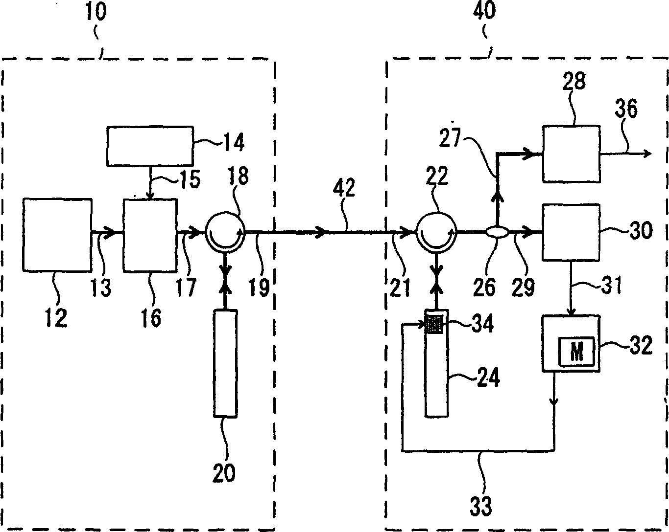
[0088] see figure 2 The block structure diagram shown here combines and explains the structure of the optical code division multiplexing transmission method and the optical code division multiplexing transmission device as the first embodiment of the present invention and the functions of each part.
[0089] The optical code division multiplexing transmission device includes a transmission unit 10 and a reception unit 40 , which are respectively connected via transmission paths 42 . The signal transmitted by the optical code division multiplexing transmission device is an optical pulse signal, and the optical pulse signal is a binary digital electrical pulse signal that will carry the information to be transmitted (the signal is a "0" or "1" The value of the binary digital signal is reflected as a pulse signal of high and low voltage) and the signal obtained by photoelectric conversion.
[0090] The transmitting unit 10 includes an optical pulse train generator 12 , a...
no. 2 Embodiment
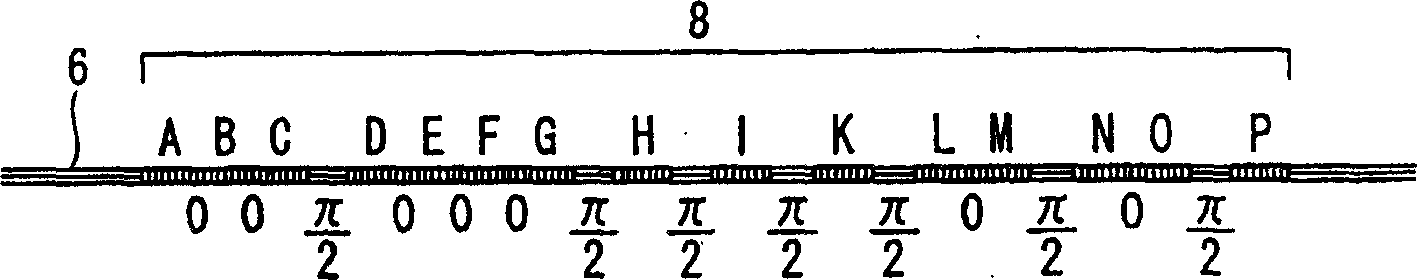
[0154] see Figure 8 The block structure diagram shown together explains the structure and the function of each part of the optical code division multiplexing transmission method and the optical code division multiplexing transmission device as the second embodiment of the present invention. Hereinafter, descriptions of contents overlapping with the structure of the optical code division multiplexing transmission method and the optical code division multiplexing transmission device of the first embodiment and the functions of each part will be omitted.
[0155] The optical code division multiplexing transmission device according to the second embodiment of the present invention also includes a transmitting unit 10 and a receiving unit 140 which are connected together through a transmission path 42 and constituted. The transmitting unit 10 includes an optical pulse train generator 12 , a modulation signal generator 14 , an optical modulator 16 , a first optical circulator ...
PUM
 Abstract
Description
Claims
Application Information
 - R&D Engineer
- R&D Manager
- IP Professional
- Industry Leading Data Capabilities
- Powerful AI technology
- Patent DNA Extraction
Browse by: Latest US Patents, China's latest patents, Technical Efficacy Thesaurus, Application Domain, Technology Topic, Popular Technical Reports.
© 2024 PatSnap. All rights reserved.Legal|Privacy policy|Modern Slavery Act Transparency Statement|Sitemap|About US| Contact US: help@patsnap.com