Flush toilet
A technology for flushing toilets and toilets, applied to flushing equipment with water tanks, flushing toilets, water supply devices, etc., can solve the problems of high cost and complicated procedures, and achieve the effect of easy cleaning of toilets
- Summary
- Abstract
- Description
- Claims
- Application Information
AI Technical Summary
Problems solved by technology
Method used
Image

Examples
no. 1 example
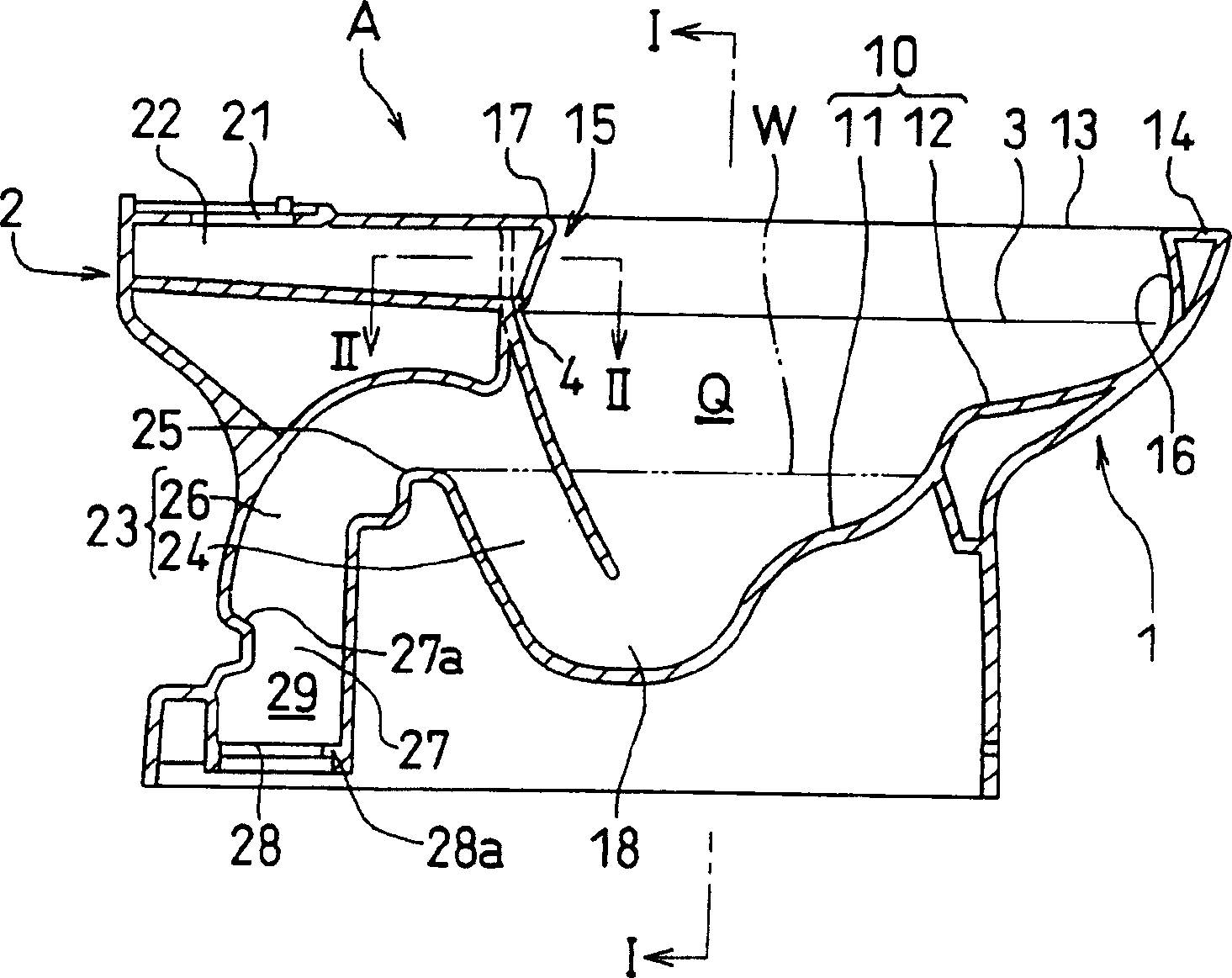
[0074] exist Figure 1 to Figure 4 The flush toilet A of the first embodiment is shown in . The water closet A is constituted as an earthenware product coated with glaze, such as figure 1 and figure 2 As shown, a basin 1 is formed at the front thereof, and a supply and drainage unit 2 is arranged at the rear of the basin 1 .
[0075] Basin 1 stores washing water in the lower part of its internal space Q, and has a bowl-shaped dirt receiving surface 10 for receiving dirt at its front. The pooled water surface 11 under the water surface is composed of the dry surface 12 located on the water surface of the pooled water portion W. The drying surface 12 is made into a smooth step shape continuous with the water accumulation surface 11 .
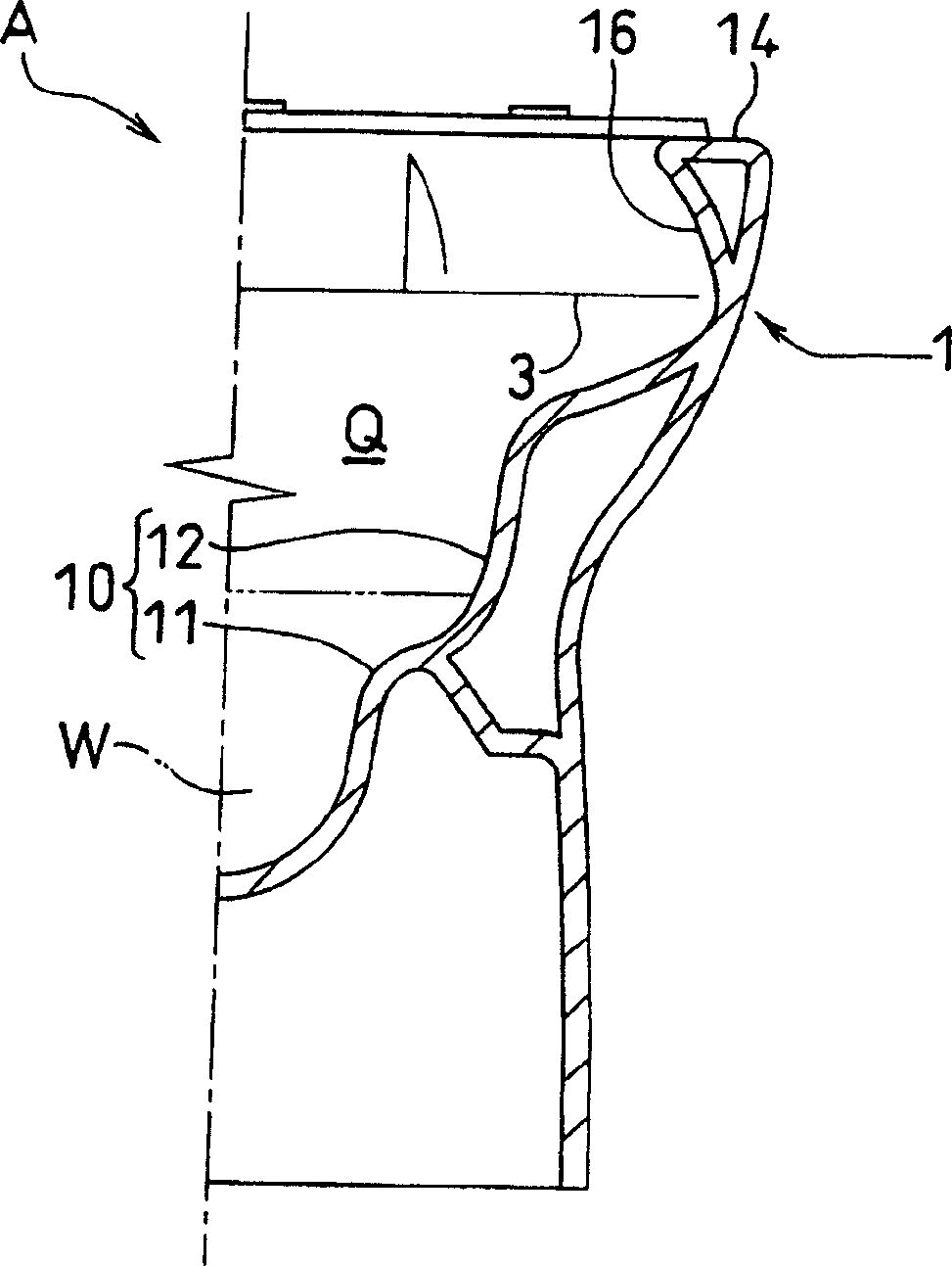
[0076] In addition, an edge portion 14 is formed with a constant width around the upper opening 13 of the bowl portion 1 .
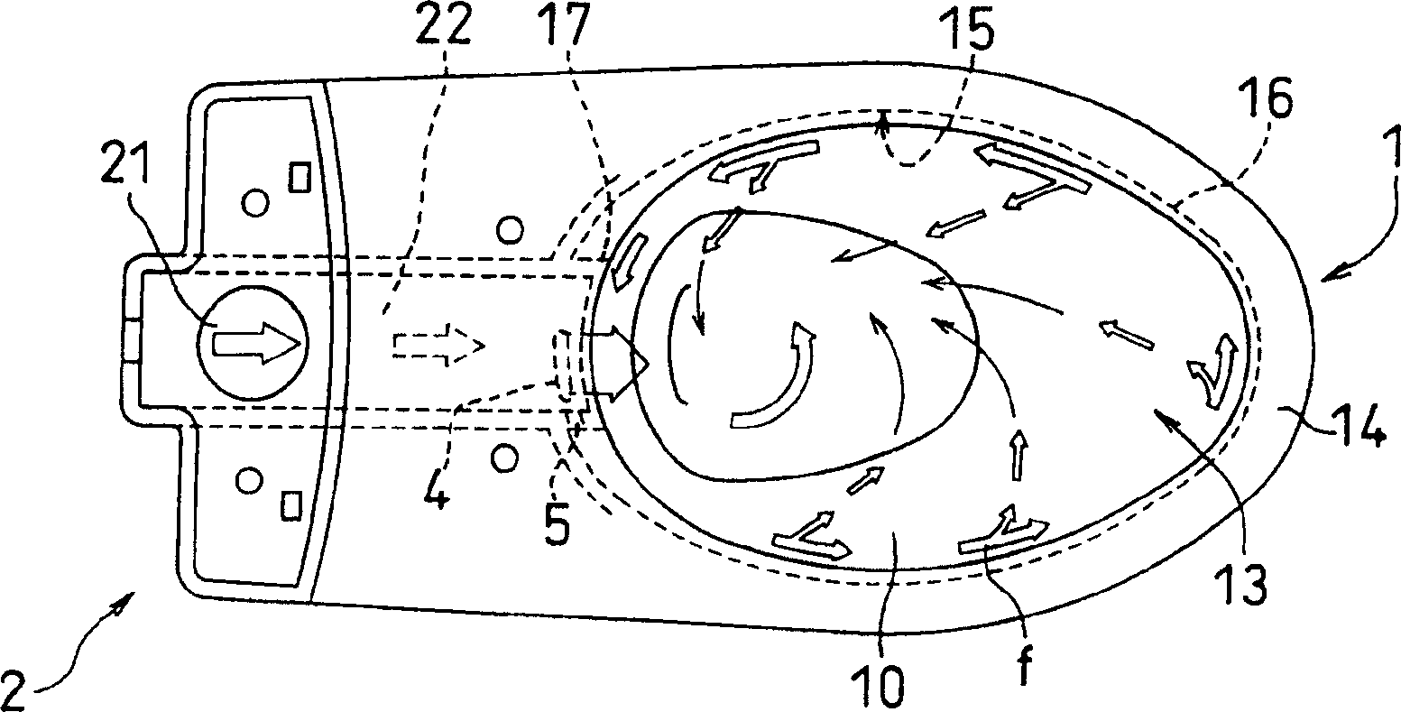
[0077] The water supply and drainage part 2 has a water supply hole 21 communicating with a flush water tank not sh...
no. 2 example
[0095] next to Figure 9 ~ Figure 11 The flush toilet A of the second embodiment shown will be described. With regard to the symbols shown in the figure, for the figure 1 The same symbols are used for the same constituent elements in the embodiments.
[0096] They are contrary to the shape of the overhanging surface that makes the washing water guide channel 16 along the entire circumference of the inner side wall surface 15 of the edge part in the previous embodiment. Here, a part of the inner side wall surface 15 of the edge part is made into an overhanging surface. As for the shape, the washing water guide passage 16 at a position facing the drain provided on the rear side of the bowl 1 is formed into a shape of a cantilevered surface.
[0097] That is to say, the bulging portion 17 forming the downward drain opening 4 and the lateral drain opening 5 as the drain portion is provided on the rear side of the basin portion 1 as in the first embodiment. The inner side wall ...
no. 3 example
[0103] Explained below Figure 17 ~ Figure 2 The water closet of the third embodiment shown in 0. Although its washing water guide channel 16 is made into a cantilevered surface shape along the entire circumference of the inner side wall surface 15 of the edge part like the first embodiment, but, unlike the first embodiment, it is located at the bottom of the basin part 1. Above the inlet 18 of the drainage flow path, and above the water surface near the water surface of the water accumulation part W in the basin 1, a forced washing water discharge port 40 is provided. The water guide channel 16 flows into the drainage channel inlet 18 . In addition, regarding the symbols shown in the drawings, the same symbols are used for the same constituent elements as those of the first embodiment.
[0104] That is, if Figure 17 As shown, as in Embodiment 1, a part of the inner side wall surface 15 of the edge part forming the partition wall between the water guide passage 22 and the ...
PUM
 Abstract
Description
Claims
Application Information
 - R&D
- Intellectual Property
- Life Sciences
- Materials
- Tech Scout
- Unparalleled Data Quality
- Higher Quality Content
- 60% Fewer Hallucinations
Browse by: Latest US Patents, China's latest patents, Technical Efficacy Thesaurus, Application Domain, Technology Topic, Popular Technical Reports.
© 2025 PatSnap. All rights reserved.Legal|Privacy policy|Modern Slavery Act Transparency Statement|Sitemap|About US| Contact US: help@patsnap.com