
Image detector for bank notes

A technology of image detection and detection device, which is applied in the direction of coin acceptance device, banknote authenticity inspection, image data processing, etc., and can solve the problems of increasing costs

Active Publication Date: 2005-02-02
LAUREL PRECISION MACHINES
View PDF1 Cites 21 Cited by
  • Summary
  • Abstract
  • Description
  • Claims
  • Application Information

AI Technical Summary

Problems solved by technology

[0007] When distinguishing the authenticity, currency type and defect of banknotes, in order to improve the identification accuracy, the image on one side of the front and back of the banknote, the image on the opposite side of the front and back of the banknote and the front and back of the banknote are respectively transmitted images, and then identify them comprehensively, but when performing this discrimination, if the banknote image detection device disclosed in the above-mentioned Japanese Patent Document 1 is used, it is necessary to detect the image on one side of the front and back directions of the banknote. The first light-emitting and receiving unit having the first image detection sensor and the first luminous body, the second light-emitting and receiving unit having the second image detection sensor and the second luminous body for detecting the image on the opposite side of the front and back of the banknote, and The light-emitting unit with the third light-emitting body and the light-receiving unit with the third image detection sensor that detect the transmitted image of the front and back of the banknote require three image detection sensors to receive the respective light, thus increasing the cost

Method used


Image

  • Image detector for bank notes
  • Image detector for bank notes
  • Image detector for bank notes

Examples


Embodiment Construction

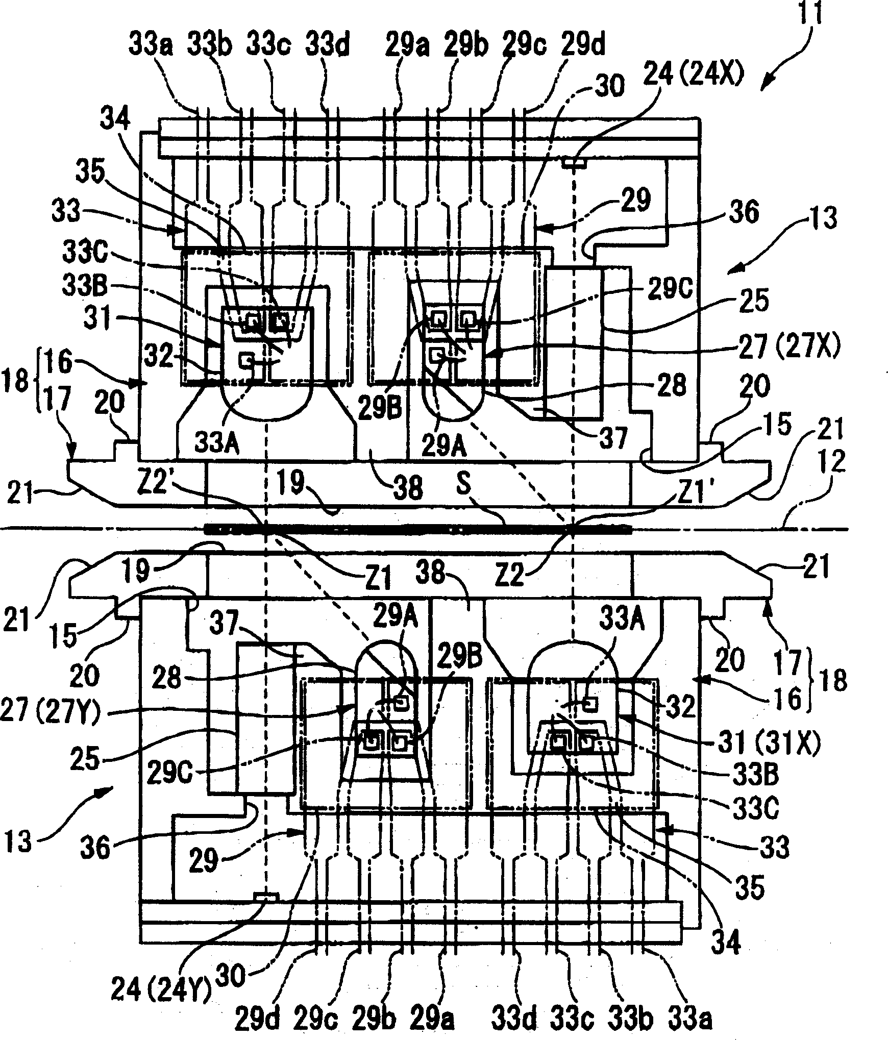
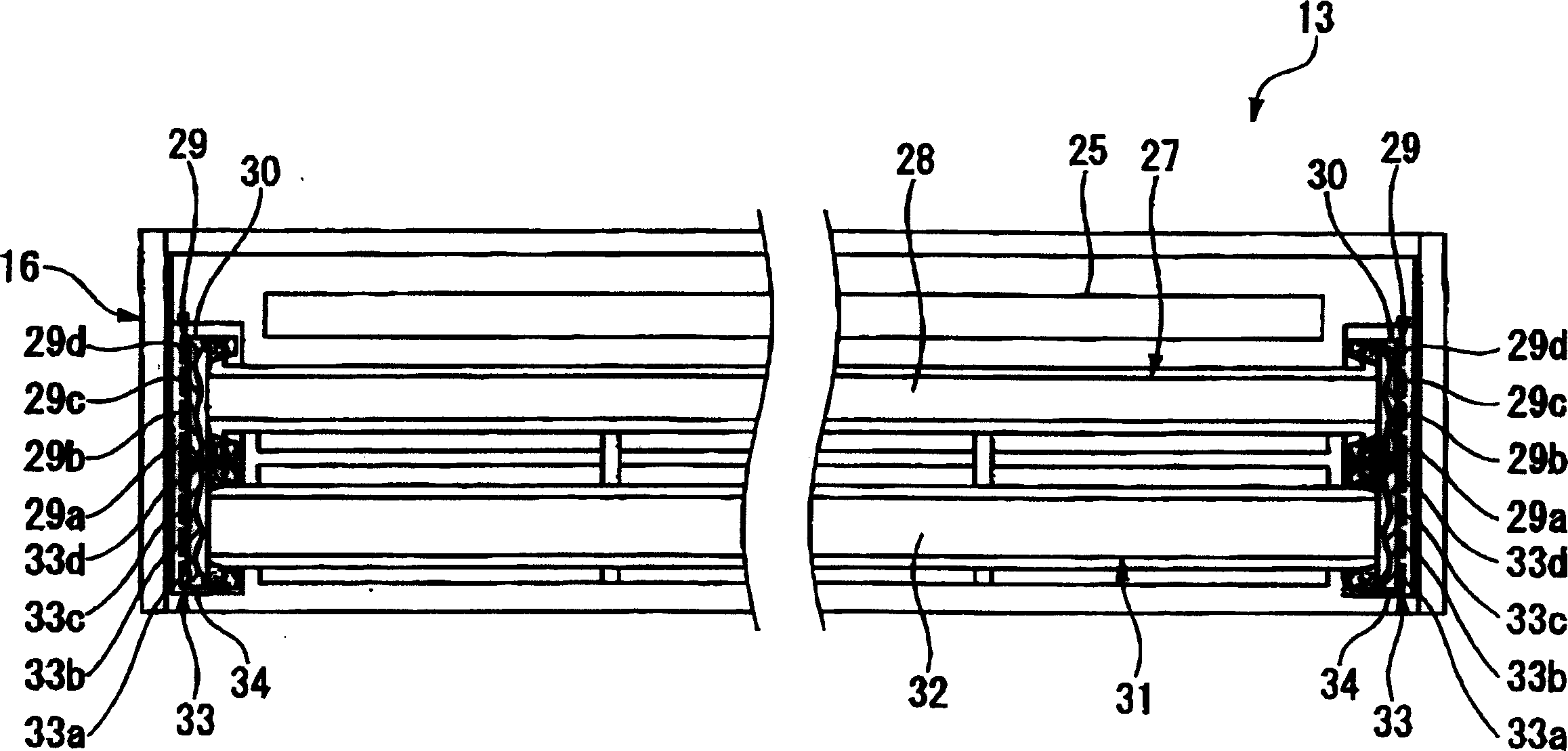
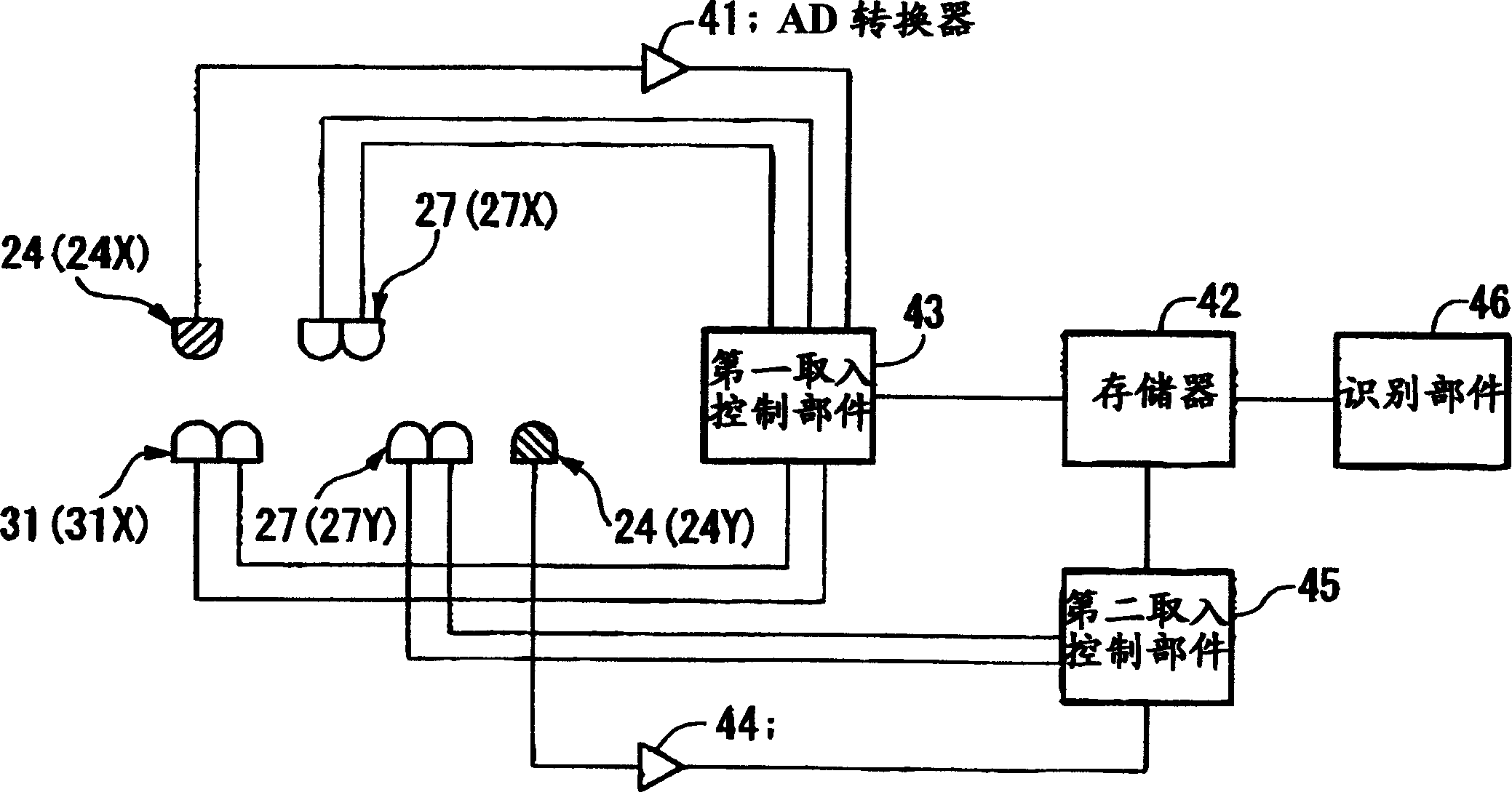
[0035] Refer to the following Figure 1 ~ Figure 4 , the banknote image detection device according to the first embodiment of the present invention will be described.

[0036] like figure 1 As shown, the banknote image detection device 11 of the first embodiment is provided with a pair of detection units 13 having the same structure, and the pair of detection units 13 are disposed opposite to each other across the banknote transport path 12 that transports the banknote S linearly. .

[0037] Detection unit 13 its length direction ( figure 1 The size in the direction perpendicular to the paper surface) is larger than the thickness direction ( figure 1 In the up and down direction) in the size and width direction ( figure 1 The dimension on the left-right direction in ) is an elongated shape. The detection unit 13 is provided with a unit body 18 composed of an elongated box-shaped container 16 provided with an opening 15 on one side in the thickness direction of the detecti...


PUM


Abstract

An object is to provide an image detector for bank notes which enables the cost to be lowered. Accordingly this has: a light emitting device 31 (31X) which is arranged facing an image detection sensor 24 (24X), and which irradiates light of a plurality of different wavelengths ranges towards a bank note on a bank note transportation path 12, and detects light of the light which has transmitted through the bank note with an image detection sensor 24 (24X); a light emitting device 27 (27X) which is provided on the same side as the image detection sensor 24 (24X), which irradiates light of a plurality of different wavelengths ranges towards a bank note S, and detects light of the light which is reflected from the bank note with the image detection sensor 24 (24X); an image detection sensor 24 (24Y) provided on the opposite side to the image detection sensor 24 (24X); and a third light emitting device 27 (27Y) provided on the same side as the second image detection sensor 24 (24Y), which irradiates light of a plurality of different wavelength ranges towards the bank note S, and detects light of the light which is reflected from the bank note S with the image detection image detection sensor 24 (24Y).

Description

technical field [0001] The present invention relates to a banknote image detection device used for distinguishing banknotes. Background technique [0002] As a technology related to the banknote image detection device used for distinguishing the authenticity, currency type, and defects of banknotes, there is a technology that irradiates the banknotes with light from a light emitting unit arranged on the side facing the banknote conveying path, and is used on the opposing banknote conveying path. The technique of detecting the transmitted light by the light-receiving unit arranged on the opposite side of the banknote, and the technology of irradiating light from the light-emitting part of the light-emitting and receiving unit on the side opposite to the banknote conveyance path to the banknote and detecting the reflected light by the light-receiving part of the same light-emitting and receiving unit (For example, refer to Japanese Patent Document 1). In addition, technology ...

Claims


Application Information

Patent Timeline
Patent Type & Authority Applications(China)
IPC IPC(8): G06T1/00G07D7/12G07D7/182
CPCG07D7/18G07D7/121G07D7/181G07D11/225G07D7/12G07D2207/00G07D2211/00
Inventor 辻敬二笠井俊雄善木智义
Owner LAUREL PRECISION MACHINES
Learn More