
Cleansing device

A technology for cleaning devices and objects to be cleaned, applied to cleaning equipment, cleaning methods and utensils, refurbishing/cleaning record carriers, etc., capable of solving problems such as unstable CO2 generation and inability to independently control the temperature of nozzle 18

Inactive Publication Date: 2005-02-02
FUJI ELECTRIC DEVICE TECH CO
View PDF1 Cites 8 Cited by
  • Summary
  • Abstract
  • Description
  • Claims
  • Application Information

AI Technical Summary

Problems solved by technology

In order to prevent this, the above-mentioned infrared heater 21 is used for temperature control, but since the temperature of the nozzle 18 cannot be independently controlled, sometimes CO 2 The generation is unstable

Method used


Image

  • Cleansing device
  • Cleansing device
  • Cleansing device

Examples


Embodiment Construction

[0035] The present invention will be described in detail below with reference to the accompanying drawings.

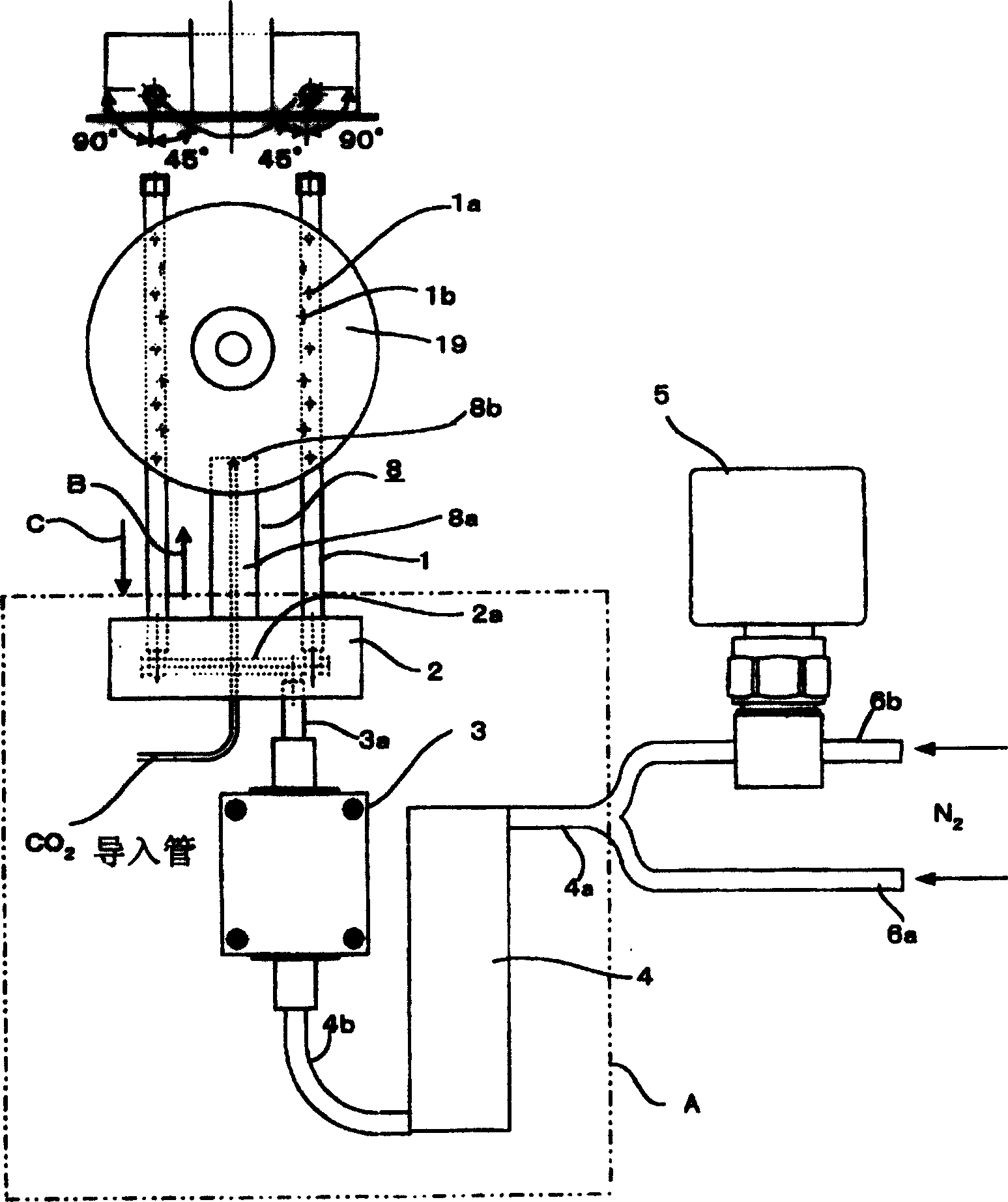
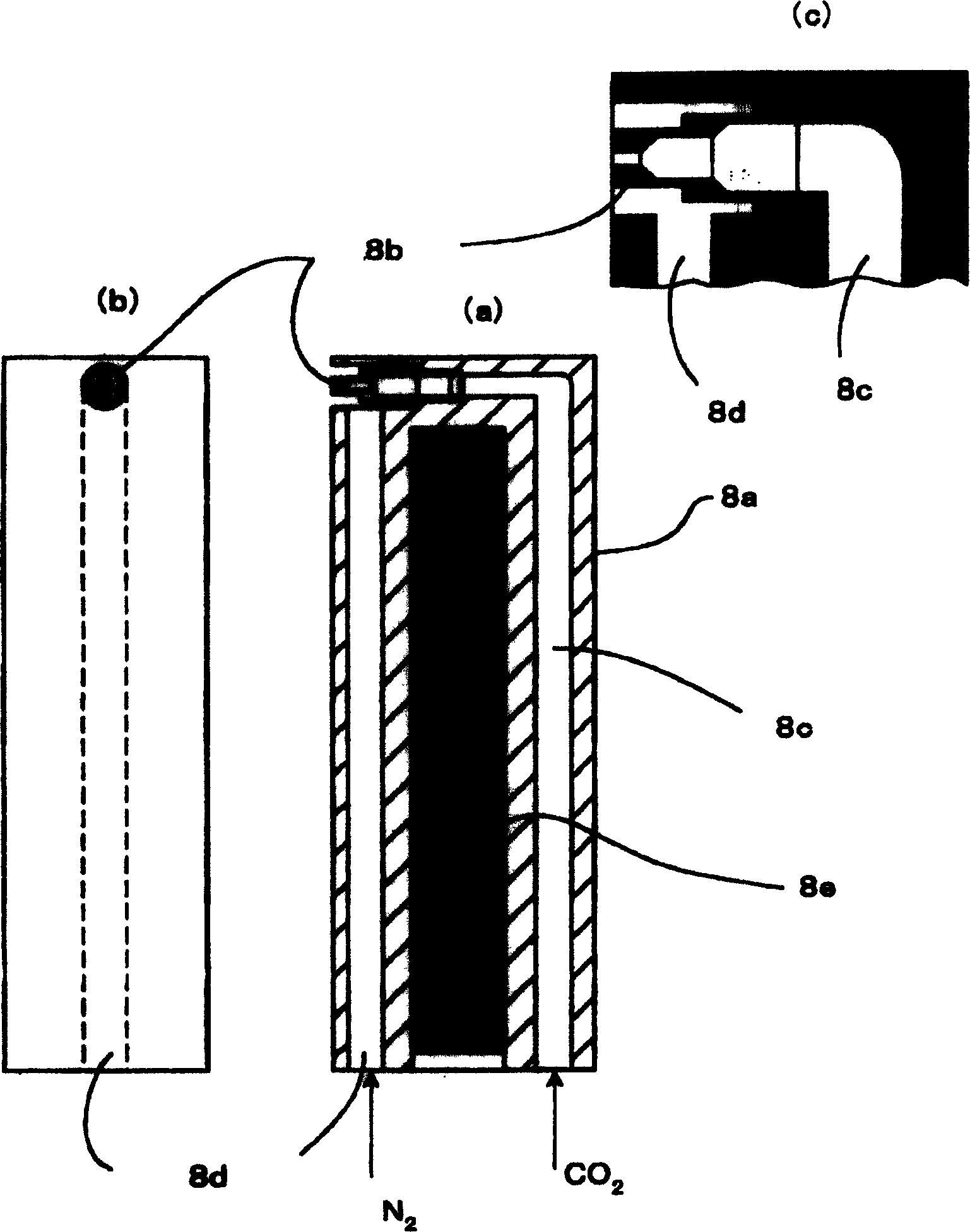
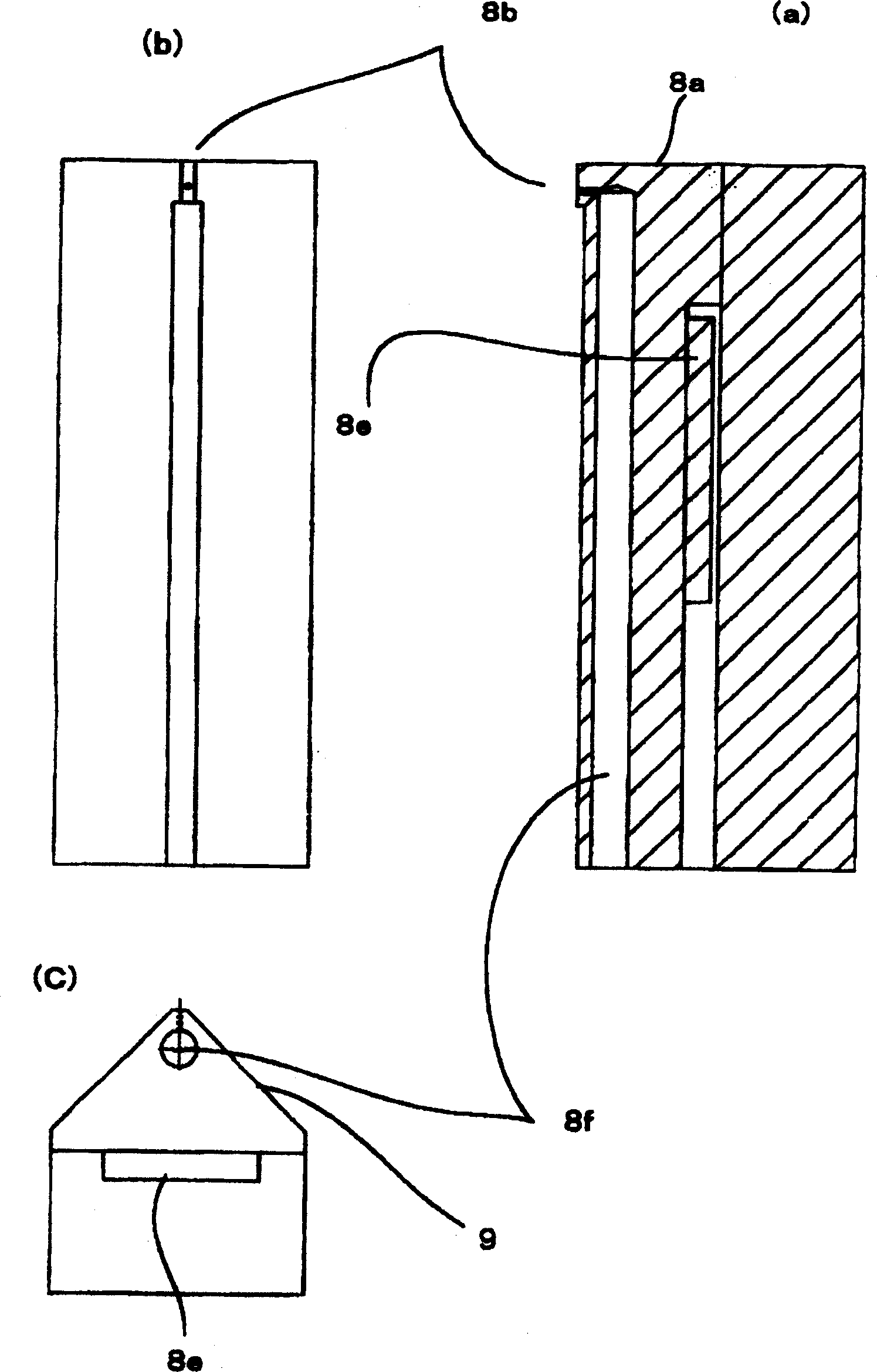
[0036] figure 1 It is a configuration diagram of main parts showing an example of an embodiment of the cleaning device of the present invention. In the figure, part A surrounded by double-dot dash line is the insulation room, which is omitted in the figure, and it uses heat insulating material to prevent heat exchange with the outside. A heater block 4, a filter 3 and a support member 2 are placed in the heat preservation chamber. In the figure, one of these pipes is disposed between the center and the peripheral edge of the object 19 to be cleaned. Since the main purpose is to prevent dew condensation on the object 19 to be cleaned, it is desirable to install four pipes on the front surface and the back surface. But at least one will do if it prevents condensation.

[0037] On the pipe 1, two series of holes 1a, 1b are formed in the length direction, these holes ...


PUM


Abstract

This cleaning apparatus which cleans the object to be cleaned by injecting a solvent upon the object from a nozzle has a gas blowing means which blows a heated gas upon the surface of the object for preventing the occurrence of dew condensation on the surface of the object. This apparatus is constituted to move to the surface of the object at cleaning time and to retreat from the object at non-cleaning time. In addition, this apparatus is also constituted to blow the heated gas at a small flow rate at the non-cleaning time and at a large flow rate at the cleaning time.

Description

technical field [0001] The invention relates to a cleaning device for cleaning and removing fine particles and organic matter on the surfaces of hard disk media and silicon wafers. Background technique [0002] When processing hard disk media, silicon wafers, or glass plates such as liquid crystal displays, it is required to minimize the unevenness of the surface, and due to microfabrication, the surface must be cleaned safely so that no fine particles and organic matter remain. [0003] Japanese Unexamined Patent Publication No. 2003-1208 discloses a cleaning device for cleaning the surface of such a silicon wafer or the like. [0004] Figure 5 It is a configuration diagram of the cleaning device described in the above publication. In the figure, 11 is CO as a cleaning agent (hereinafter referred to as solvent). 2 The high-pressure gas storage cylinder, the CO inside it 2 It is divided into a liquid part 111 whose temperature is T and a gas part 112 whose pressure is Po...

Claims


Application Information

Patent Timeline
Patent Type & Authority Applications(China)
IPC IPC(8): G11B5/84A47L5/14B08B3/00B08B5/00B08B5/02B08B7/00B08B7/02B08B7/04B24C1/00G11B23/50H01L21/00H01L21/304
CPCB24C1/003B08B5/02B08B7/0021H01L21/67051B08B7/02
Inventor 吉田隆司菊地长保岩崎元明幅谷仓夫矢野达郎城间贵浩
Owner FUJI ELECTRIC DEVICE TECH CO
Learn More