
A CMOS voltage comparator

A voltage comparator, MOS tube technology, applied in electrical components, logic circuits, generating electrical pulses, etc., can solve problems such as slow conversion speed, affect the accuracy of the comparator, and cannot work normally, and achieve fast comparison speed and input dynamic range. Large, comparatively high-precision effects

Inactive Publication Date: 2005-01-19
SHANGHAI HUAHONG INTEGRATED CIRCUIT
View PDF0 Cites 8 Cited by
  • Summary
  • Abstract
  • Description
  • Claims
  • Application Information

AI Technical Summary

Problems solved by technology

[0003] Due to the existence of the offset voltage of the op amp, it will affect the accuracy of the comparator
And because the open-loop gain of the op amp is very large, a small offset voltage may cause the circuit to saturate
thus not working properly
[0004] Due to the lack of positive feedback, the speed of the comparator is limited by the slew rate (SLEW RATE) of the op amp. Due to the use of a single-stage op amp, the switching speed is very slow, resulting in a very slow slew rate.

Method used


Image

  • A CMOS voltage comparator
  • A CMOS voltage comparator
  • A CMOS voltage comparator

Examples


Embodiment Construction

[0025] The technical solution of the present invention will be further described below in conjunction with the embodiments and the accompanying drawings.

[0026] figure 2 is a structural block diagram of an embodiment of the CMOS voltage comparator of the present invention, in which two stages of amplifiers are cascaded, such as figure 2 mentioned, including:

[0027] The first amplifier 21, its first output end is connected with the first input end through a switch 26, its second output end is connected with the second input end through a switch 26, two switches are opened or closed at the same time, can be regarded as unified Operational, so marked with the same symbol in the figure;

[0028] The second amplifier 22, the input end is connected with the output end of the first amplifier 21, its first output end is connected with the first input end through a switch 26, and its second output end is connected with the second input end through a switch 26, which The two sw...


PUM


Abstract

The invention is a CMOS voltage comparer, a multistage amplifier, where, for each one, the first output end is connected with the first input end by a switch and the second output end connected with the second input end by a switch, the two switches are opened or closed at the same time; the input end of each amplifier is connected with the output end of the previous amplifier and the switches of all the amplifiers are opened or closed at the same time; a double-arrival single-converting circuit with two input ends connected with two output ends of the last amplifier; a multistage output reshaping circuit, where one input end is connected with one output end of the double-arrival single-converting circuit; DC isolating capacitors, situated in front of the input ends of all the amplifiers and the double-arrival single-converting circuit; a first switch, where an input signal is connected to the primary amplifier through the first switch and then an DC isolating capacitor; a second switch, where the other input signal is grounded through the second switch and the second switch and all the switches of the multistage amplifier are opened or closed at the same time.

Description

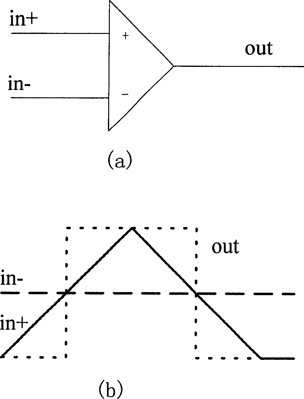
technical field [0001] The invention relates to a voltage comparator, in particular to a CMOS voltage comparator composed of multi-level circuits. Background technique [0002] In the traditional comparator in the integrated circuit, the operational amplifier is usually used as the comparator, and the comparison function is realized by utilizing the characteristic of the large open-loop gain of the operational amplifier. If the input voltage of the positive terminal is higher than that of the negative terminal, the output will be a high level; if the input voltage of the positive terminal is lower than that of the negative terminal, a low level will be output. In this way, the comparison of the input voltage of the positive and negative input terminals is realized. The functional block diagram and working principle diagram of the circuit are shown in figure 1 as shown, figure 1 (a) is a functional block diagram, figure 1 (b) is the working principle diagram, in which the...

Claims


Application Information

Patent Timeline
Patent Type & Authority Applications(China)
IPC IPC(8): H03K3/16H03K19/0948
Inventor 陈良生
Owner SHANGHAI HUAHONG INTEGRATED CIRCUIT
Learn More