Light guiding plate, illumination device, and liquid crystal display device
A technology for lighting devices and light guides, which is applied in the field of light guides, liquid crystal display devices, and lighting devices, and can solve problems such as damage to the appearance of liquid crystal display devices, reduced black display contrast, and increased component costs, achieving good visibility, High contrast, brightening effect
- Summary
- Abstract
- Description
- Claims
- Application Information
AI Technical Summary
Problems solved by technology
Method used
Image

Examples
Embodiment 1
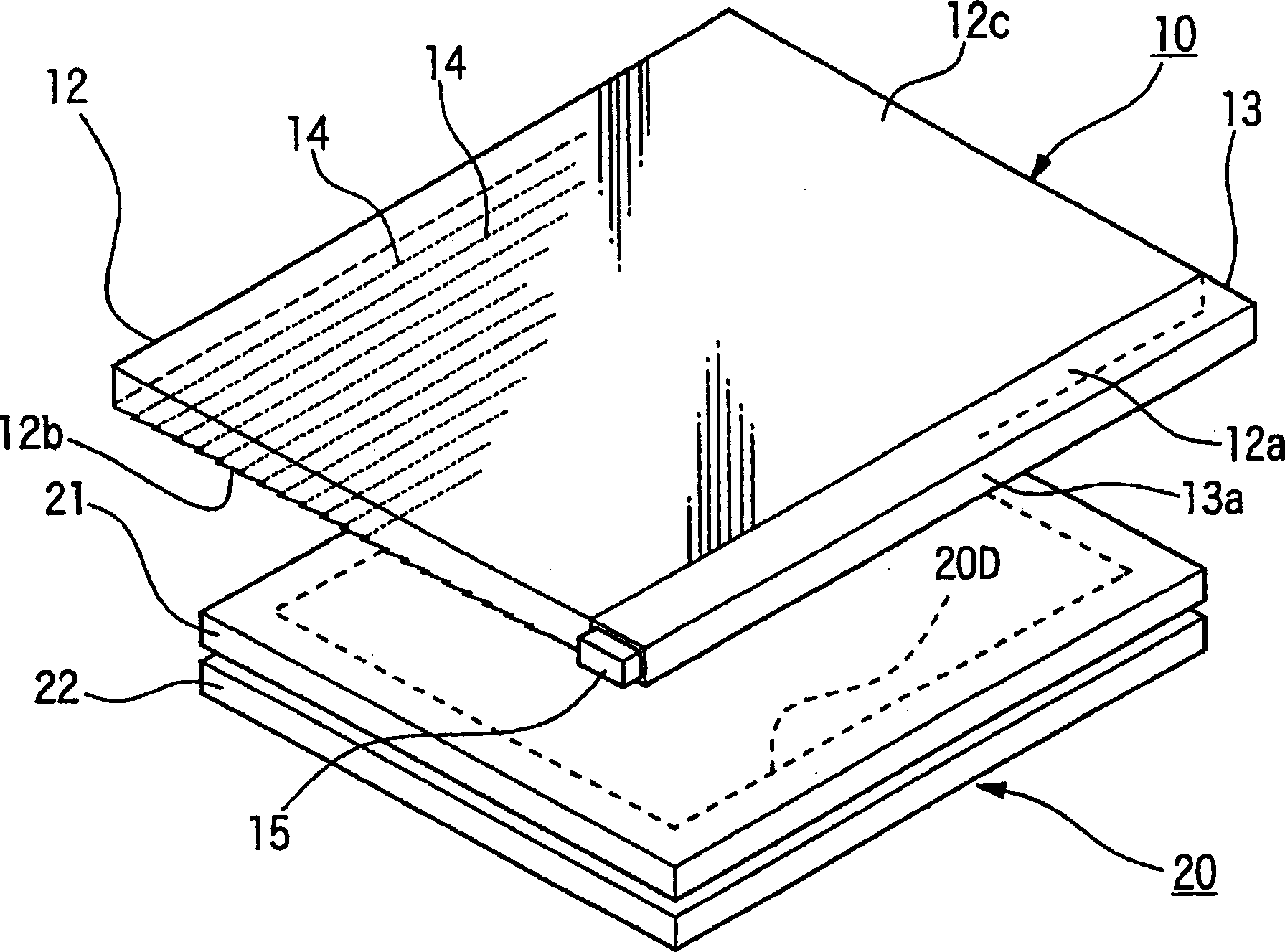
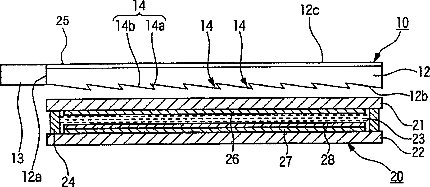
[0163] In this example, for Figure 1 ~ Figure 3 light guides of the novel shape shown, and Figure 20 The shown conventional light guides were compared in terms of the amount of emitted light and the amount of light leaked when the inclination angle of the inclined portion from which the propagating light was emitted was optimized with respect to the incident angle of the propagating light.
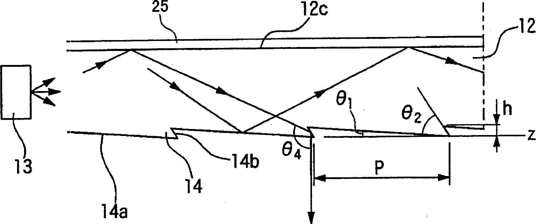
[0164] Table 1 is a table that summarizes and expresses the parameters of each part of the light guide body compared in this example. In this table, the novel shape represents image 3 light guide shown, the existing shape represents Figure 20 light guide shown. Moreover, θ in the novel shape 1 , θ 2 Respectively image 3 The angle of inclination shown, θ in the existing shape 1 , θ 2 Respectively Figure 20 The angle of inclination shown. Moreover, the size of the light guides is 70mm W×50mm L×1.0mm t, and the material is all acrylic resin (refractive index: 1.48).
[0165] Next...
Embodiment 2
[0168] Secondly, yes in image 3 The protrusion 14 formed on the outgoing surface 12b of the light guide body 12 of the present invention shown, and the Figure 20 The reflection characteristics of the protrusions 114 formed on the upper surface of the shown conventional light guide 112 with respect to propagating light incident from inside the light guide were compared. The comparison results are shown in Tables 2 to 5 below. Table 2 and Table 3 show the reflection characteristics of the light guide of the present invention, that is, the protrusions of a novel shape, and Tables 4 and 5 show the reflection characteristics of the protrusions of a conventional shape. In addition, Table 2 and Table 4 show the results when the constituent material of the light guide is Arton (trade name: manufactured by JSR Corporation), and Table 3 and Table 5 show the results when the constituent material of the light guide is acrylic resin. .
[0169] In these tables, the angles of incidence ...
Embodiment 3
[0186] In this example, for the Figure 1 ~ Figure 3 The light guide of the present invention of the novel shape shown, and Figure 20 The brightness and contrast of the liquid crystal display device with the light guide body of the conventional shape shown were compared.
[0187] As a light guide of novel shape 3, making image 3 The inclination angle θ shown 1 2.8°, θ 2 45°, the size of the light guide body is 70mm W×50mm L×1.0mm t, the material is acrylic resin (refractive index 1.48), and the protective layer laminated on the light guide body is made of urine with a thickness of 500 Å (50nm). Alkacrylate-based hard coating material that is UV-curable.
[0188] Furthermore, as the light guide of the conventional shape 3, the Figure 20 The inclination angle θ shown 1 2.8°, θ 2 45°, the size of the light guide is 70mm W×50mm L×1.0mm t, the material is acrylic resin (refractive index 1.48), and the structure that omits the front mask is used.
[0189] Furthermore, as a ...
PUM
| Property | Measurement | Unit |
|---|---|---|
| Tilt angle | aaaaa | aaaaa |
| Tilt angle | aaaaa | aaaaa |
| Refractive index | aaaaa | aaaaa |
Abstract
Description
Claims
Application Information
 - R&D
- Intellectual Property
- Life Sciences
- Materials
- Tech Scout
- Unparalleled Data Quality
- Higher Quality Content
- 60% Fewer Hallucinations
Browse by: Latest US Patents, China's latest patents, Technical Efficacy Thesaurus, Application Domain, Technology Topic, Popular Technical Reports.
© 2025 PatSnap. All rights reserved.Legal|Privacy policy|Modern Slavery Act Transparency Statement|Sitemap|About US| Contact US: help@patsnap.com