


Quick Research
Generate reliable direction feasibility study reports for your R&D in just a few steps.

Technical Q&A
Discover and master advanced knowledge NOW. Basics, ideas, possibilities, all at once.

Find Solutions
As an expert in R&D theories, this can generate solutions to your technical problems instantly.

Evaluate Feasibility
Analyze your overall solution with one click, know your potential R&D risks in advance.

Monitor Landscape
Get weekly tech updates, stay abreast of the latest tech innovations and key insights.
Air disinfection machine
An air sterilizer and air filter technology, applied in the directions of disinfection, atomization, deodorization, etc., to achieve the effects of excellent performance, rapid humidification, and uniform distribution
- Summary
- Abstract
- Description
- Claims
- Application Information
AI Technical Summary
Problems solved by technology
Method used
Image

Examples
Embodiment 1
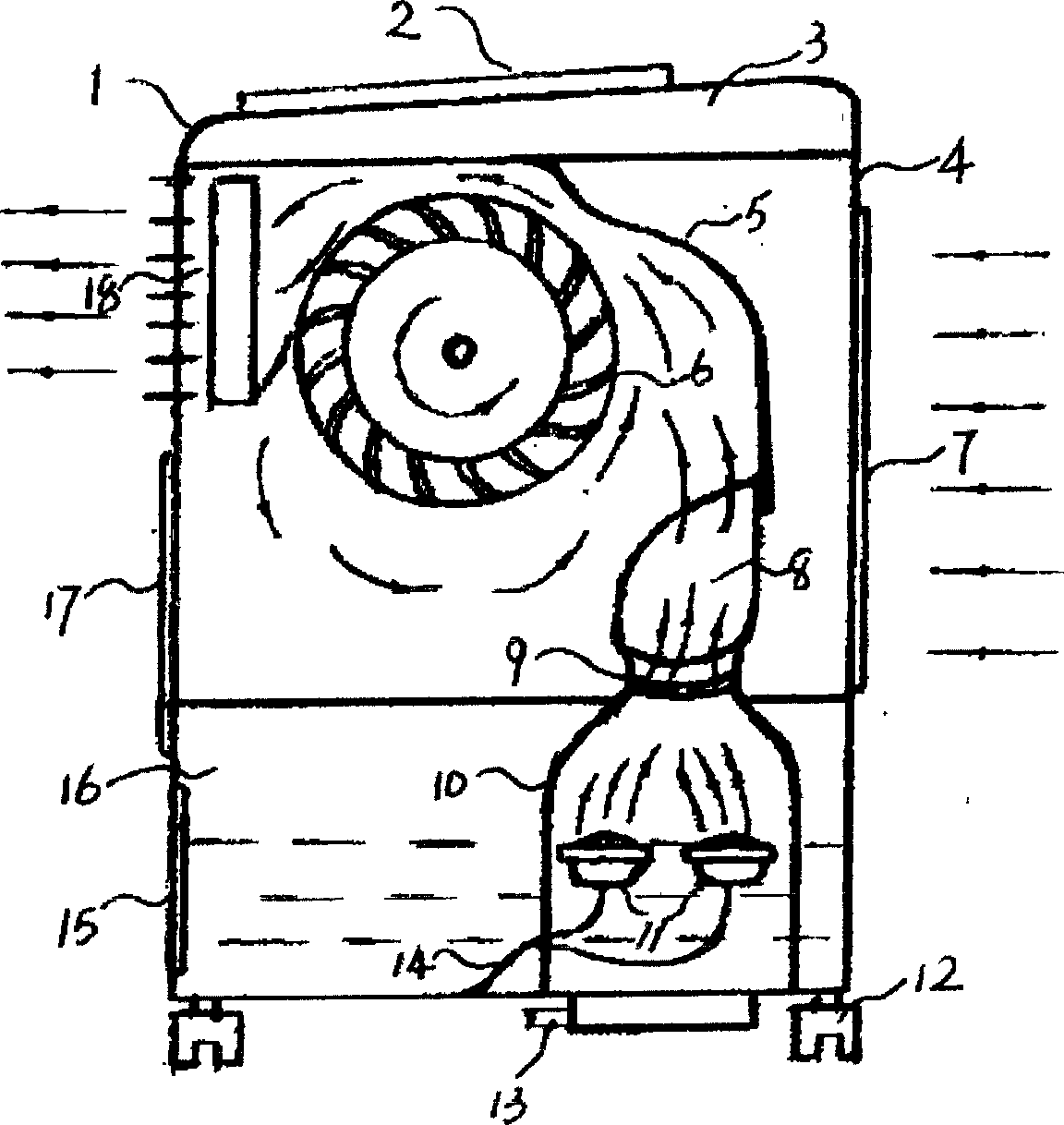
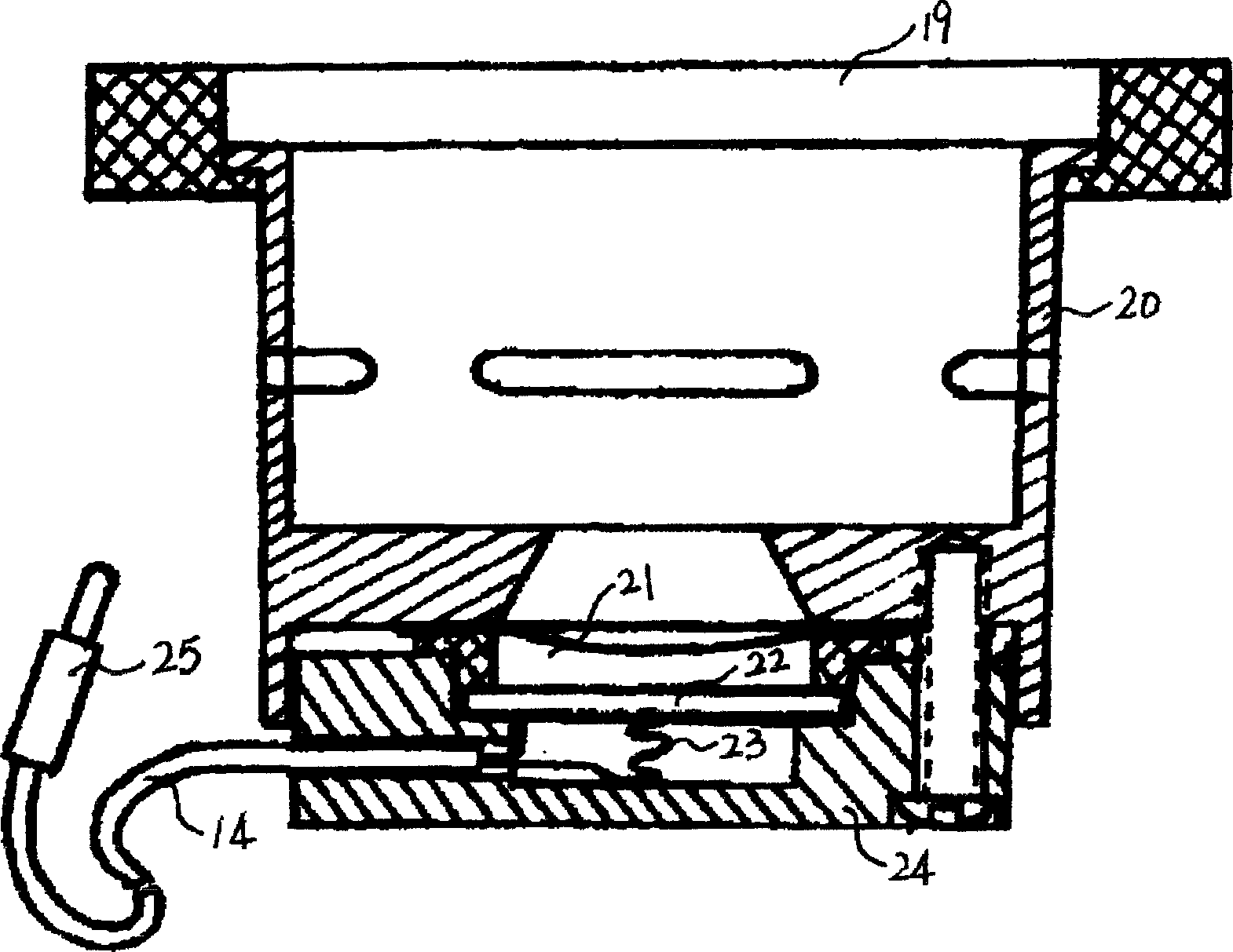
[0022] Embodiment 1 as attached figure 1 As shown, inside the box 1 with air filter 7 and rear cover 4, fan 6, ultrasonic high-frequency generating device 3, liquid storage tank 16, ultrasonic atomization and atomization gas lifting filter device 8.9.10.11.14 , the air outlet vertical wind direction adjustment device 18 and the electrical control system 2. as attached image 3 The shown ultrasonic atomizing gas lifting filter device is installed in the liquid storage tank 16, and the upper edge of the wind-gathering mist guide head 8 just meets the lower edge of the wind guide cover 5 of the fan, and is connected and fixed with a hasp. make move. Close the liquid discharge valve 13 at the bottom of the liquid storage tank, and then fill the correctly prepared disinfectant into the liquid storage tank from the front door 17, because the lower wall of the ultrasonic atomization gas lifting filter device has pores and the liquid storage tank 16 Connected, the internal and exte...
Embodiment 2
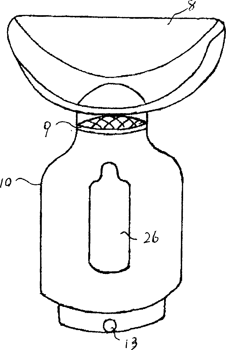
[0023] Embodiment 2 For the machine that is determined to be configured with 2 ultrasonic atomization transducers, the other structures are the same as in Embodiment 1, and the ultrasonic atomization gas lifting filter device is as follows: Figure 4 The manufacturing setup shown: that is, the atomization chamber 10 is formed by two interconnected garden tubes forming a "∩"-shaped smooth transition, and is connected with a wind-gathering mist head 8 through a smooth transition to form an atomized gas lifting filter. Device: A long waist hole 26 is respectively provided on the wall surface of the atomizing gas chamber 10 facing forward with the door 17 open. When in use, the ultrasonic atomized gas lifting filter device is arranged in the liquid storage tank 16 as required, so that the upper edge of the wind gathering mist guide head 8 is connected to the lower edge of the wind guide cover 5 of the fan 6, and fixed with a hasp OK, attach the two figure 2 The shown self-floati...
Embodiment 3
[0024] Embodiment 3 For the machine that is determined to be equipped with 3 ultrasonic atomization transducers, other structures are the same as those in Embodiment 1 and 2, and the ultrasonic atomization gas lifting filter device is as follows: Figure 5 The structural manufacturing settings shown are: the atomizing gas chamber 10 is composed of 3 interconnected garden tubes, which are connected with 1 wind-gathering and mist-guiding head 8 through a circular transition to form an atomizing gas lifting and filtering device. The wall of the air chamber 10 facing forward to open the door is respectively provided with a long waist hole 26; the ultrasonic atomization lifting filter device is arranged in the liquid storage tank 16 according to requirements, so that the upper edge of the wind gathering mist guide head 8 is in contact with the fan 6 The lower edges of the air guide cover 5 are connected and fixed with a hasp, and then the attached figure 2The three self-floating a...
PUM
 Abstract
Description
Claims
Application Information
 - R&D Engineer
- R&D Manager
- IP Professional
- Industry Leading Data Capabilities
- Powerful AI technology
- Patent DNA Extraction
Browse by: Latest US Patents, China's latest patents, Technical Efficacy Thesaurus, Application Domain, Technology Topic, Popular Technical Reports.
© 2024 PatSnap. All rights reserved.Legal|Privacy policy|Modern Slavery Act Transparency Statement|Sitemap|About US| Contact US: help@patsnap.com