Motor control equipment
A technology of motor control and motor, which is applied in the direction of control system, motor control, excitation or armature current control, etc. It can solve the problems of temperature surge inside the PWM control module, reduce the reliability of the protection motor control equipment, etc., and achieve the goal of improving reliability. Effect
- Summary
- Abstract
- Description
- Claims
- Application Information
AI Technical Summary
Problems solved by technology
Method used
Image
Examples
no. 1 example
[0023] The present invention will be described in detail with reference to various embodiments in which the motor control apparatus is applied to an electrically driven fan system for an automobile engine cooling apparatus.
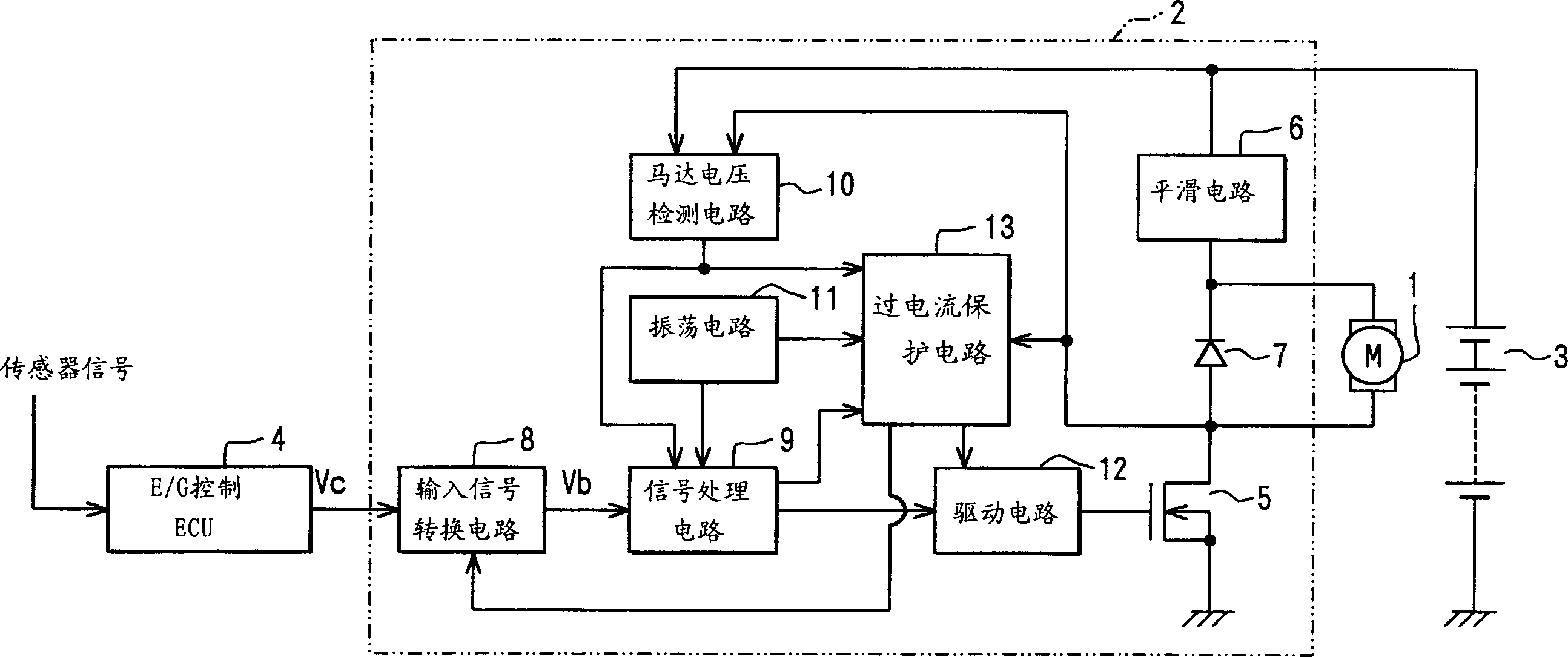
[0024] refer to figure 1 , the DC motor 1 acts as a driver for a low-pressure air compressor fan (not shown) for cooling engine cooling refrigerant flowing through a heat exchanger such as a radiator. The motor control device 2 controls the rotation speed of the motor 1 . The battery 3 supplies power to the motor control device 2 through an ignition switch (not shown). It is worth noting that in some configurations, the battery 3 directly supplies power to the motor control device 2 .
[0025] The voltage supplied to the motor 1 determines the rotational speed of the low pressure air compressor fan. The motor control device 2 adjusts the level of voltage by employing a pulse width modulation (PWM) control method that applies switching of the output of ...
no. 2 example
[0097] exist Figure 6 The second embodiment shown in is basically the same as figure 1 The same as the first embodiment shown in . However, in the second embodiment, the resistor 100 is connected between the negative terminal of the motor 1 and the connection point between the MOSFET 5 and the freewheeling diode 7 . In addition, the voltage appearing across the ends of the resistor 100 is supplied to the overcurrent protection circuit 13 .
[0098] exist Figure 7 In the overcurrent protection circuit 13 shown, the motor current IM is taken as the current voltage ( Figure 8 S3) in the detection. The overcurrent protection circuit 13 includes a low-end overcurrent detection threshold voltage setting circuit 140 for setting a low-end overcurrent detection threshold voltage Va( Figure 8 in S1). The low-side judgment comparator 150 compares the low-side overcurrent detection threshold voltage Va output by the low-side overcurrent detection threshold voltage setting circui...
PUM
 Abstract
Description
Claims
Application Information
 - R&D
- Intellectual Property
- Life Sciences
- Materials
- Tech Scout
- Unparalleled Data Quality
- Higher Quality Content
- 60% Fewer Hallucinations
Browse by: Latest US Patents, China's latest patents, Technical Efficacy Thesaurus, Application Domain, Technology Topic, Popular Technical Reports.
© 2025 PatSnap. All rights reserved.Legal|Privacy policy|Modern Slavery Act Transparency Statement|Sitemap|About US| Contact US: help@patsnap.com


