
Plamsa display panel display device and its driving method

A plasma and display device technology, applied in static indicators, televisions, instruments, etc., can solve the problems of low withstand voltage limit, write pulse fluctuations of discharge cells, and rising costs, achieve good image display, avoid circuit heating, Avoid cost-increasing effects

Inactive Publication Date: 2004-10-06
PANASONIC CORP
View PDF0 Cites 4 Cited by
  • Summary
  • Abstract
  • Description
  • Claims
  • Application Information

AI Technical Summary

Problems solved by technology

[0026] However, in the above-mentioned conventional driving method, there are following problems: the withstand voltage limit of the data driver IC generally used in the panel driving section 40 is low, and the write pulse applied during the write period cannot be sufficiently ensured depending on the situation. Happening
Therefore, the withstand voltage limit of the data driver IC may also become a big obstacle here.
[0028] In addition, since the chemical characteristics of the phosphors of the RGB colors used in the PDP are different from each other, it has the following properties: even though the same power is input, the write pulses corresponding to the discharge cells of each color will fluctuate, so the RGB colors The discharge probability (lighting rate) of the cells in the phosphor is different
In order to avoid the impact caused by write pulse fluctuations, as a countermeasure, it can be considered that the driving voltages corresponding to the data electrodes 32 of various colors are set to a high value as much as possible (that is, they are all set to the values ​​on the discharge cells with the highest lighting rate). write pulse), but here the withstand voltage limit of the data driver IC also becomes an obstacle
[0029] As a solution to this problem, it is conceivable to use a high withstand voltage IC for the data driver IC, but since its price is usually high, it will increase the cost, so it should be avoided
In addition, even if a high-output driver IC is used, there will be a new problem of increased power consumption of the PDP display device, which is not ideal considering the recent tendency towards larger screens.

Method used


Image

  • Plamsa display panel display device and its driving method
  • Plamsa display panel display device and its driving method
  • Plamsa display panel display device and its driving method

Examples


Embodiment 1

[0053] 1-1. Configuration of PDP display device (panel drive unit)

[0054] In the PDP display device of the first embodiment, the PDP unit 10 is substantially the same as the above-mentioned conventional structure, but the structure of the panel driving unit 40 connected thereto has a different feature. Next, the panel driving unit 40 will be described.

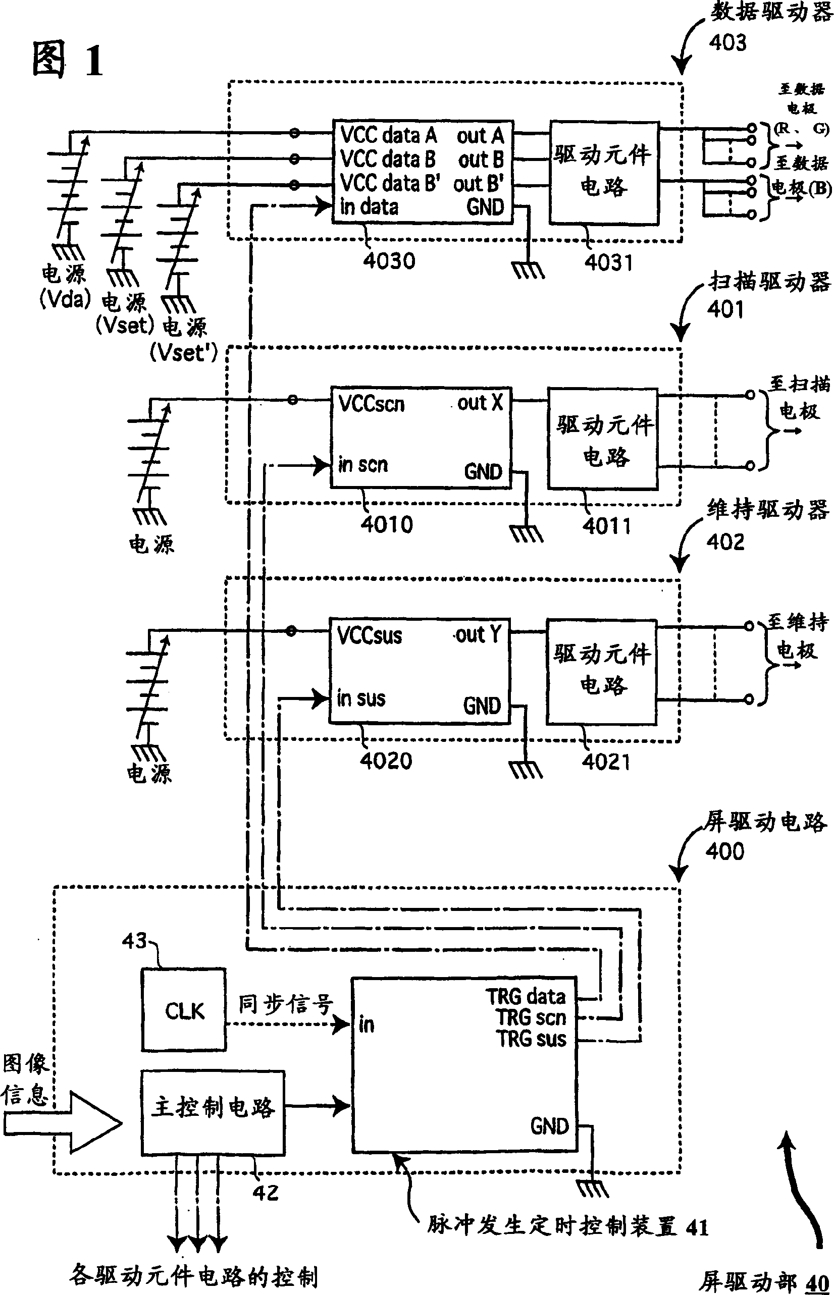
[0055] FIG. 1 is a diagram showing the peripheral configuration of a panel driving unit in the first embodiment.

[0056] The panel driving section 40 shown in FIG. 1 is composed of (1) a data driver 403 connected to each data electrode 32, (2) a scan driver 401 connected to each scan electrode (X electrode) 25, (3) and each sustain electrode (Y electrode). electrode) 24 connected to the sustain driver 402 and (4) the panel drive circuit 400 that controls the operation of these drivers 401 to 403 and the like.

[0057] A sustain pulse generation timing control device 41 (hereinafter referred to as "pulse control device 41"...

Embodiment 2

[0148] 2-1. PDP display device in Embodiment 2

[0149] The device structure of Embodiment 2 of the present invention is substantially the same as that of Embodiment 1, so repeated descriptions are omitted here. The present embodiment 2 is characterized by a driving waveform process.

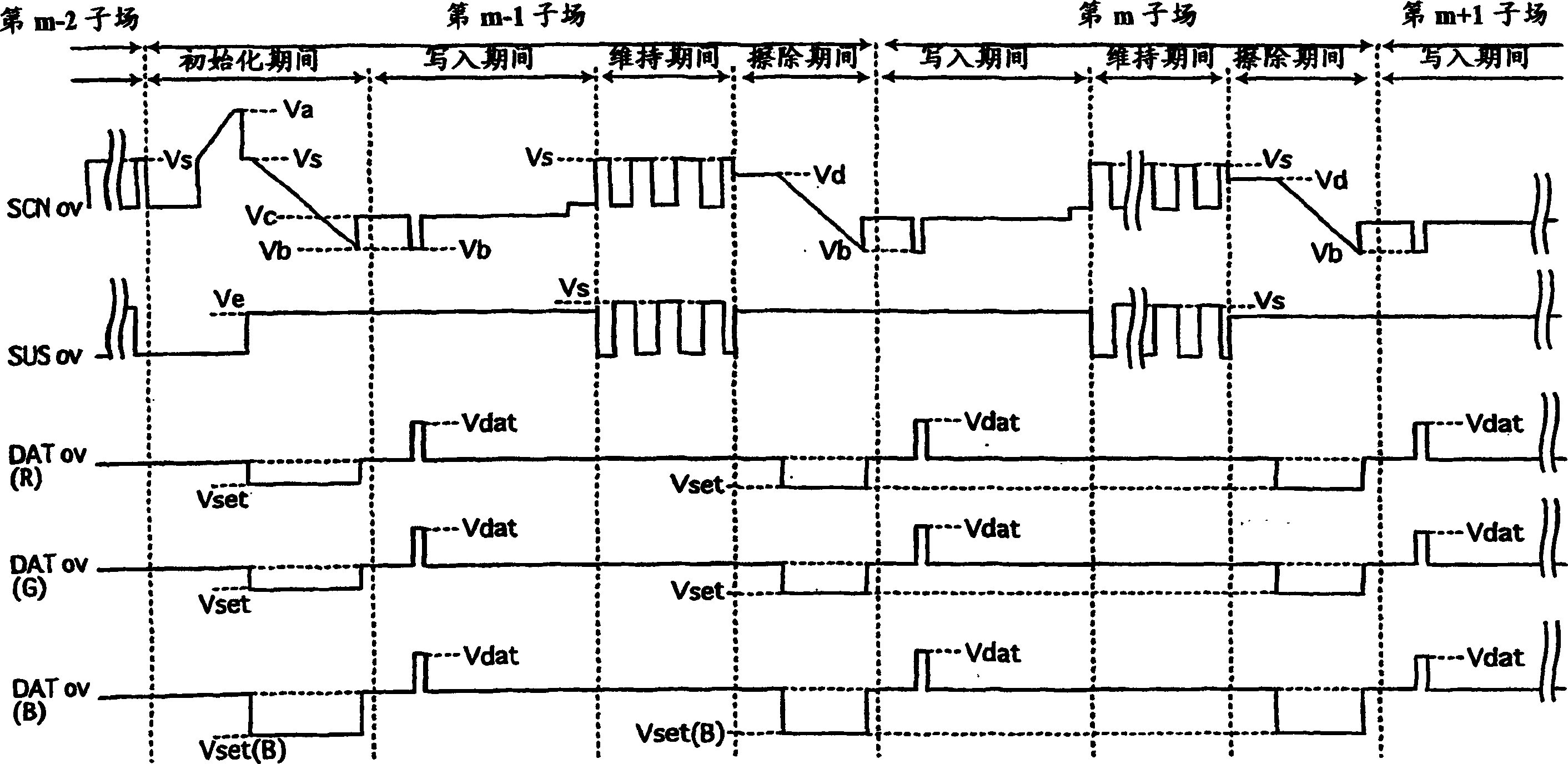
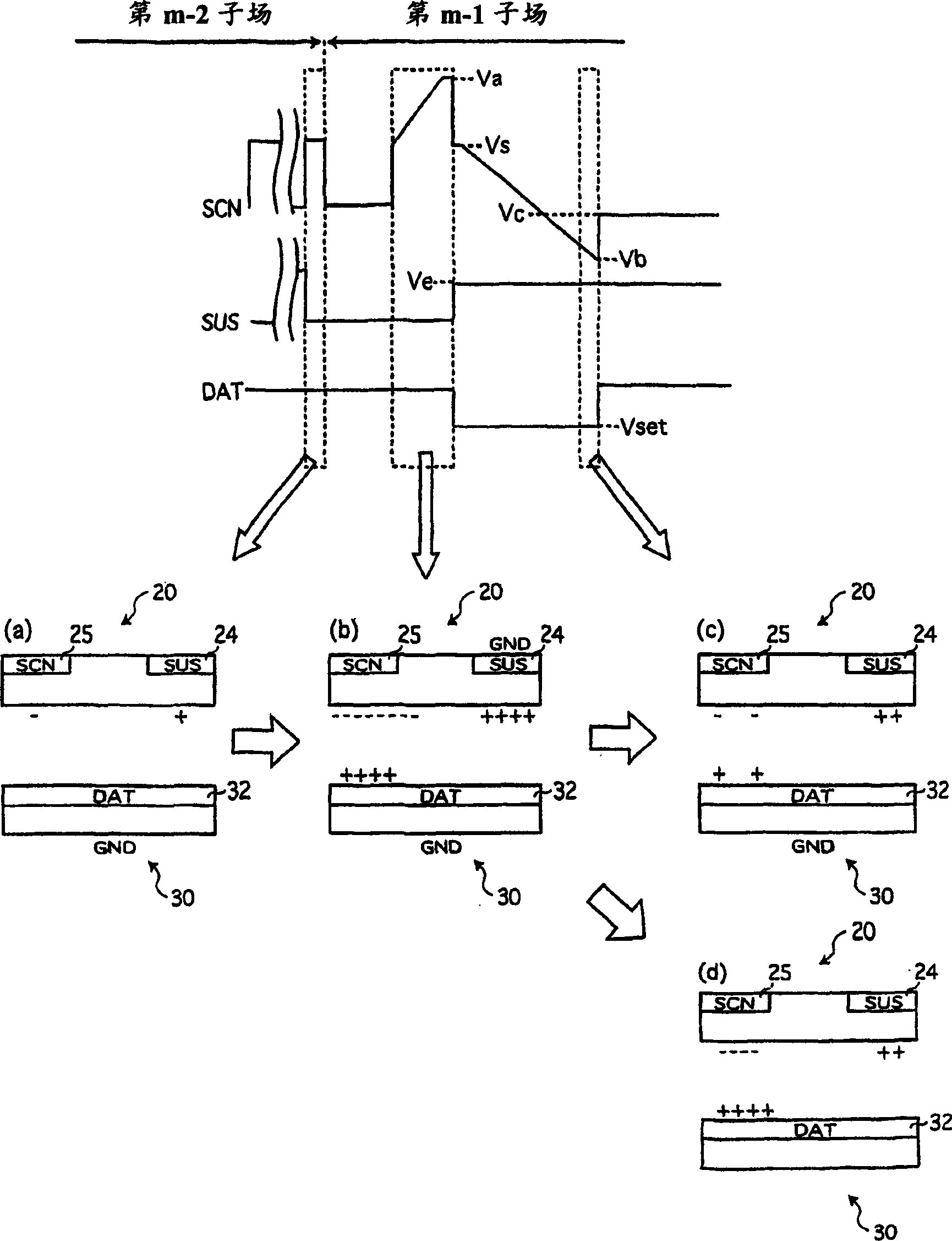
[0150] That is, the second embodiment is characterized in that in the initialization period or erasing period immediately after the application of the sustain electrode 24 to the sustain electrode 24 in the subfield is completed, the incremental voltage is applied to the scan electrode 25 and the voltage is applied to the data electrode 32 at the same time. Apply a positive polarity pulse.

[0151] 2-2. Driving process of PDP display device

[0152] The driving process of the PDP display device of the second embodiment is as follows. according to Figure 6 The driving process of the PDP display device will be described in the driving waveform timing diagram (m-1th subfield) of FIG.

[0153]...


PUM


Abstract

A method of driving a plasma display device that includes a plurality of scanning electrodes, a plurality of sustaining electrodes, and a plurality of data electrodes is such that, when m is any given integer, the data electrodes are applied with a negative polarity pulse when a voltage applied to the scanning electrodes gradually decreases during the initialization period, if a final pulse in a sustain period of an (m-1)-th subfield is applied to the scanning electrodes and an m-th subfield includes an initialization period. If the final pulse in the sustain period of the (m-1)-th subfield is applied to the sustaining electrodes and the m-th subfield includes the initialization period, the data electrodes are applied with a positive polarity pulse when a voltage applied to the scanning electrodes gradually increases during the initialization period.

Description

technical field [0001] The invention relates to a plasma display screen display device and its driving method, in particular to an improved technology for reducing power consumption during driving. Background technique [0002] Plasma display (hereinafter referred to as "PDP") excites phosphor powder to emit light through ultraviolet rays generated in gas discharge to display images. According to the type of discharge method, it is divided into alternating current (AC) type and direct current (DC) type. The AC type is characterized by being superior to the DC type in terms of brightness, luminous efficiency, and lifetime. Among the AC types, the reflective surface discharge type is particularly excellent in brightness and luminous efficiency, and the reflective surface discharge type is the most commonly used. [0003] Figure 9 It is a perspective view schematically showing the conventional AC type PDP unit 10 . Such as Figure 9 As shown, in the structure of the PDP uni...

Claims


Application Information

Patent Timeline
Patent Type & Authority Applications(China)
IPC IPC(8): G09G3/20G09G3/288G09G3/291G09G3/292G09G3/293G09G3/294G09G3/296G09G3/298
CPCG09G3/2927G09G2310/066G09G2320/0228G09G3/2022G09G3/291G09G3/296
Inventor 真铜胜利奥村茂行仓田隆次长尾宣明村井隆一
Owner PANASONIC CORP
Learn More