
Submerged hole driller component element

A technology for down-the-hole drilling and components, which is used in drill bits, earth-moving drilling, drilling equipment, etc., can solve the problems of restricting the air discharge of the hammer drill, reducing the performance of the hammer drill, and breaking the bottom valve tube.

Active Publication Date: 2004-10-06
莱昂内尔·吉安·伯纳德
View PDF1 Cites 10 Cited by
  • Summary
  • Abstract
  • Description
  • Claims
  • Application Information

AI Technical Summary

Problems solved by technology

This will further restrict the exhaust air of the hammer drill and will result in reduced performance of the hammer drill
Another problem is that the bottom valve tube often breaks
This causes downtime for the driller as he has to pull the bit out of the hole, remove the bit from the hammer drill and replace the bottom valve tube

Method used


Image

  • Submerged hole driller component element
  • Submerged hole driller component element
  • Submerged hole driller component element

Examples


Embodiment Construction

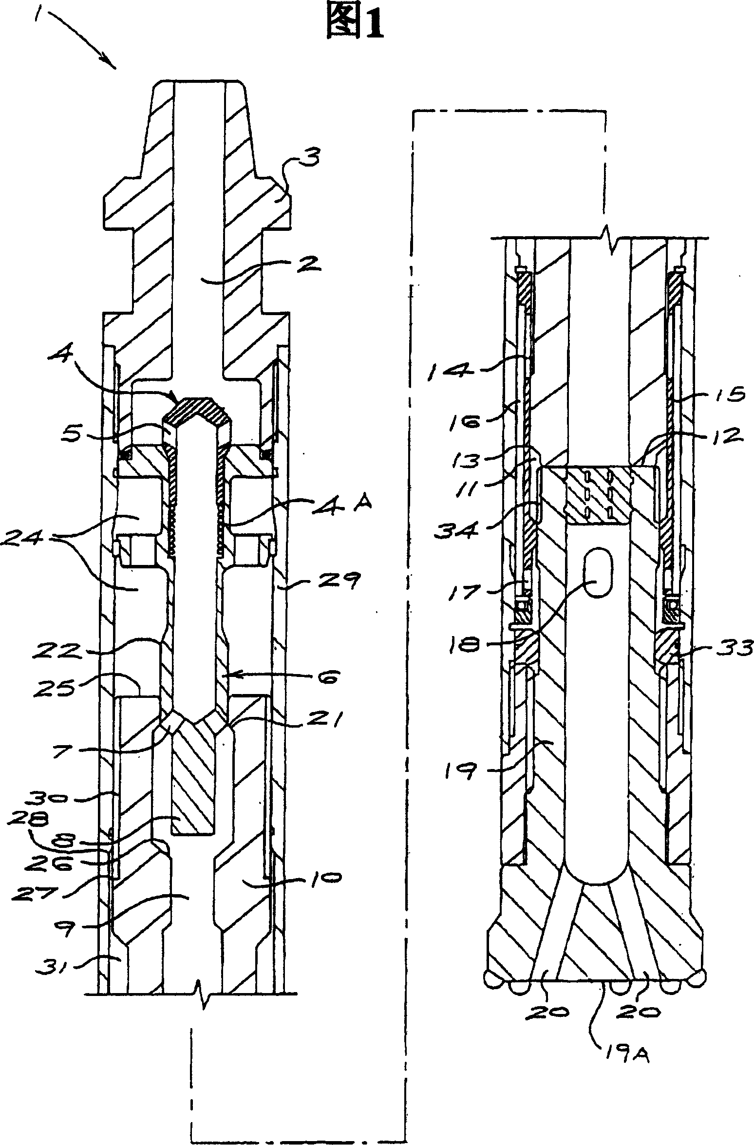
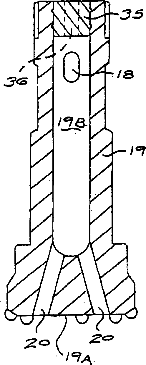
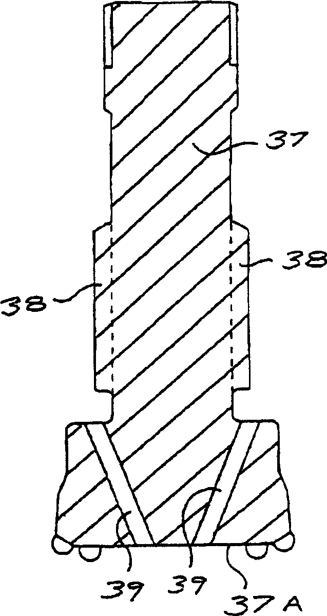
[0017] A down-the-hole hammer drill as shown in the figure comprises a drill assembly (1) according to the invention. The assembly (1) provides lifted air to the lower chamber (11) below the piston (10) through the bore (9) of the piston (10), and through the outside of the piston (10) and through at least the outside of the drill bit (19) body Part of the exhaust. Then, the exhausted air is directed through the opening (18) to the inside of the bit facet (19A), simply because it facilitates the thorough blowing of the cuttings from the underside of the bit facet (19A). Since the compressed air flows directly into the lower chamber (11) through the hole (9) of the piston (10) without deflection and makes the piston (10) reciprocate faster, thereby releasing more energy to the drill bit (19), so Hammer drills are very effective.

[0018] In this embodiment of the invention, the drill bit (19) has an opening (18) extending transversely through the wall of the drill bit (19) in...


PUM


Abstract

The invention provides a down-the-hole drill assembly having exhaust passages from upper and lower chambers past the inner end of a bit and through the body of the bit to exit through the bit face. The construction of the assembly and bit obviates a foot valve tube from the head of the bit and the disadvantages associated with this component.

Description

technical field [0001] The invention relates to a down-the-hole drilling tool assembly, in particular to an assembly without using a bottom valve pipe. Background technique [0002] Valveless down-the-hole hammer drills often must have a bit with a replaceable foot valve tube extending from the head of the bit at the impact face of the bit and piston. The bottom valve tube extends into the bore of the piston and is pulled out of the bore of the piston when the piston is removed from the drill bit. Exhaust from the upper or lower chamber is discharged into the atmosphere through the center of the bottom valve pipe through the center hole of the drill bit. [0003] When the piston hits the drill bit, the hole of the piston is engaged with the bottom valve tube, and the upper chamber exhausts through the hole of the piston passing through the center of the bottom valve tube and exhausts to the atmosphere through the hole of the drill bit. [0004] As the piston reciprocates u...

Claims


Application Information

Patent Timeline
Patent Type & Authority Applications(China)
IPC IPC(8): E21B4/14
CPCE21B4/14G07F7/005G07F9/00
Inventor 莱昂内尔·吉安·伯纳德
Owner 莱昂内尔·吉安·伯纳德
Learn More