Electric tool
A technology of electric tools and tool heads, which is applied in the technical field of vibration and can solve the problems of reducing the vibration amount of dynamic shock absorbers and the like
- Summary
- Abstract
- Description
- Claims
- Application Information
AI Technical Summary
Problems solved by technology
Method used
Image
Examples
no. 1 example
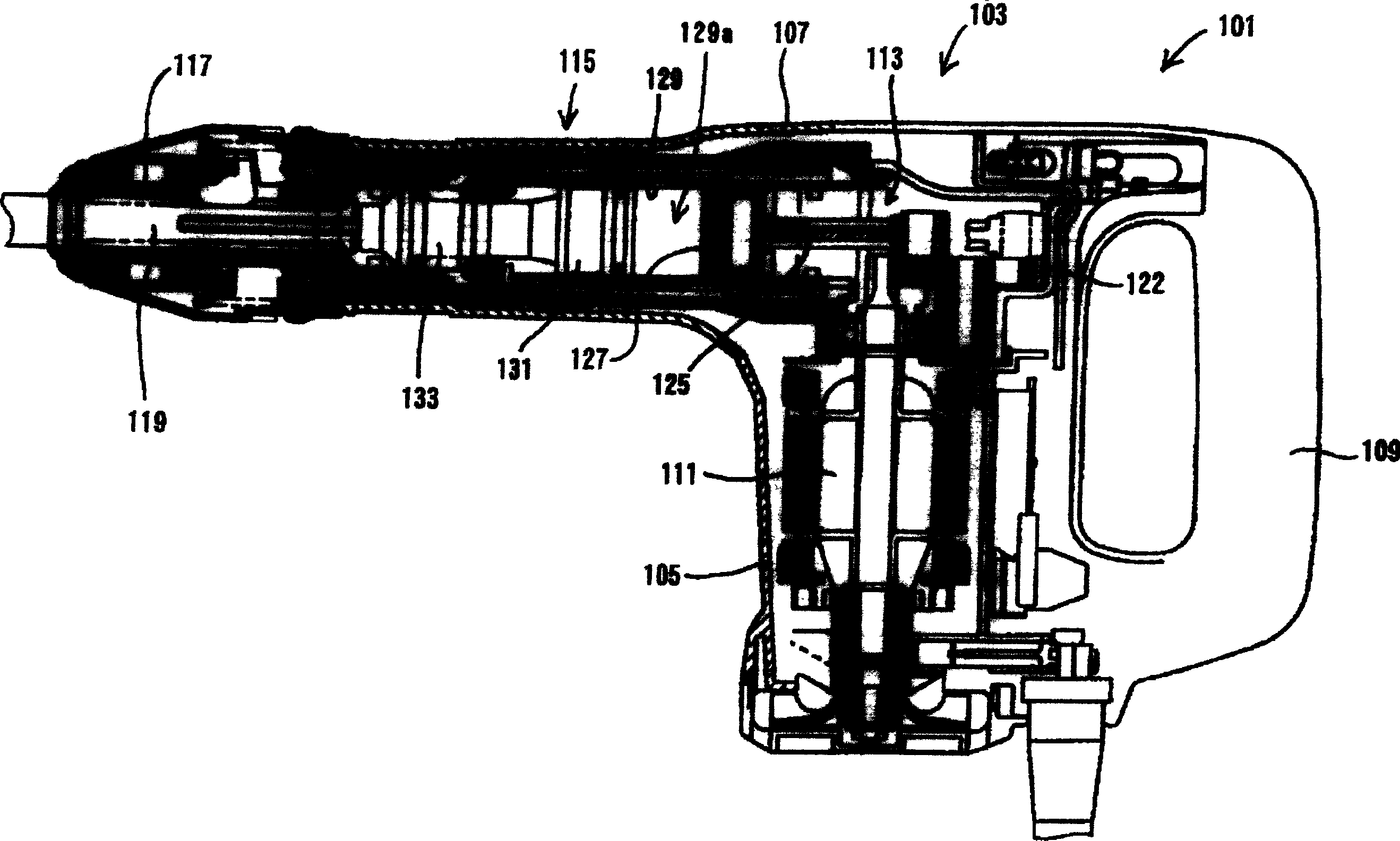
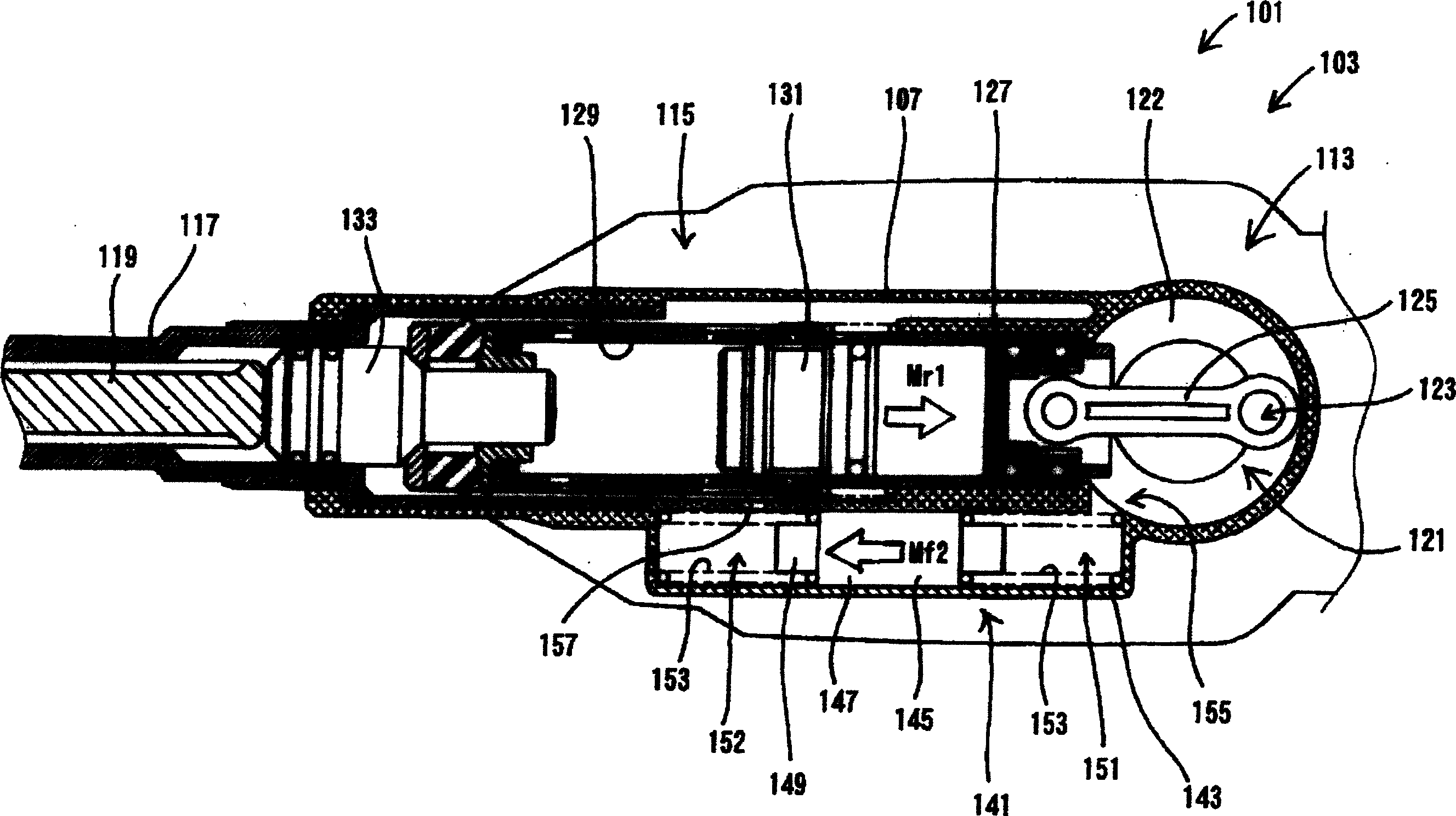
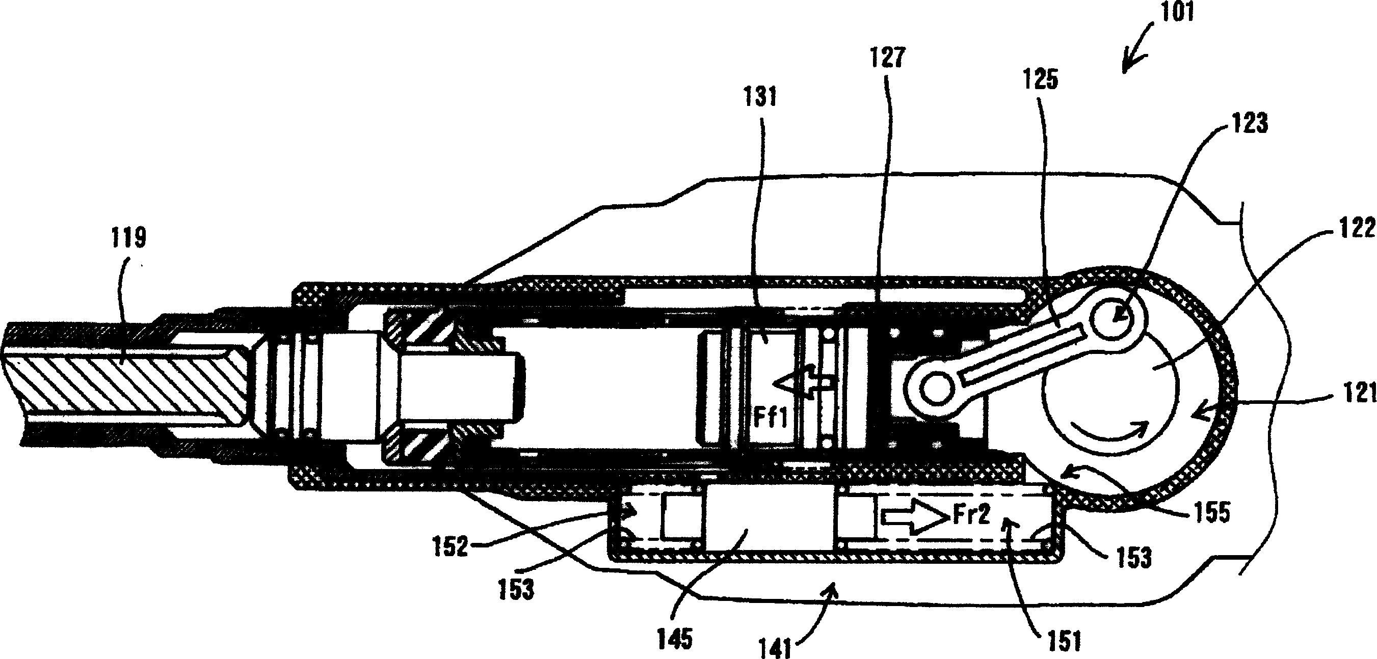
[0092] now refer to Figure 1 to Figure 5 A first embodiment of the present invention is described. What will be described is an electric hammer as a typical example of the electric power tool of the present invention. Such as figure 1 As shown, a typical electric hammer 101 according to the present embodiment includes a body 103; a tool holder 117, which is connected to the end region of the body 103; and a hammer bit 119, which is detachably connected to the tool holder On the holder 117. The hammer bit 119 is a feature corresponding to the "tool bit" of the present invention.
[0093] The body 103 includes a motor housing 105 housing a drive motor 111 , a gear housing 107 housing a motion converting mechanism 113 and an impact element 115 , and a handle 109 . The motion conversion mechanism 113 is adapted to properly convert the rotational output of the drive motor 111 into linear motion, which is then transmitted to the impact member 115 . Thus, an impact force is gen...
no. 2 example
[0112] now refer to Image 6 with Figure 7 A second embodiment of the present invention is described. In the second embodiment, the balance weight 245 of the dynamic vibration absorber 241 can be actively driven only in the case of load driving where a load is applied to the hammer bit 219 from the workpiece side. For this reason, on the periphery of the cylinder 229, a cylindrical action member 261 and a biasing spring 263 are installed.
[0113] exist Image 6In , the hammer 201 is shown in a no-load driven state, ie no load is applied to the hammer bit 219 from the workpiece side. At this time, as shown in the figure, the action member 261 is pressed to the left by the bias spring 263 . In this state, the action member 261 closes a first communicating portion 255 connecting a first action chamber 251 of the dynamic shock absorber 241 and the crank chamber 221 . The action member 261 also closes a second action chamber 252 communicating with the dynamic shock absorber ...
no. 3 example
[0119] now refer to Figure 8 with Figure 9 A third embodiment of the present invention is described. Similar to the second embodiment, the third embodiment is also configured such that the counterweight 345 of the dynamic damper 341 is actively activated only in the case of load driving when a load is applied to the hammer bit 319 from the workpiece side. to drive. However, the third embodiment is different in configuration from the second embodiment in the communication state of the crank chamber 321 under load and no-load driving. In the hammer 301 of this embodiment, a cylindrical actuator 361 and a bias spring 363 are provided on the periphery of the air cylinder 329 . The crank chamber 321 always communicates with a first action chamber 351 of the dynamic shock absorber 341 through a first communication portion 355 .
[0120] exist Figure 8 , the hammer 301 is shown in an idle drive condition with no load applied to the hammer bit 319 from the side of the workpiec...
PUM
 Abstract
Description
Claims
Application Information
 - R&D Engineer
- R&D Manager
- IP Professional
- Industry Leading Data Capabilities
- Powerful AI technology
- Patent DNA Extraction
Browse by: Latest US Patents, China's latest patents, Technical Efficacy Thesaurus, Application Domain, Technology Topic, Popular Technical Reports.
© 2024 PatSnap. All rights reserved.Legal|Privacy policy|Modern Slavery Act Transparency Statement|Sitemap|About US| Contact US: help@patsnap.com


