
Face pressure reducer of closed compressor

A compressor, airtight technology, used in mechanical equipment, machines/engines, rotary piston machines, etc., can solve the problems of low torque and wear of the rotating shaft 4, and achieve the goal of reducing surface pressure, reducing friction loss and improving efficiency. Effect

Inactive Publication Date: 2004-09-29
LG ELECTRONICS (TIANJIN) APPLIANCES CO LTD
View PDF0 Cites 2 Cited by
  • Summary
  • Abstract
  • Description
  • Claims
  • Application Information

AI Technical Summary

Problems solved by technology

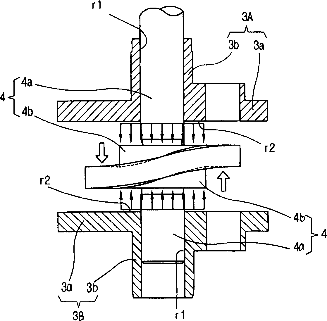
like figure 2 and image 3 As shown, in the compressor in which the shaft part 4a and the expansion part 4b of the rotating shaft 4 are formed concentrically, the torque of the rotating shaft 4 is smaller than that of the above-mentioned compressors with different structures, and the concentrated load is applied to the diameter bearing a relatively small load. On the above-mentioned thrust bearing portion 3a on the opposite side of the bearing portion 3b, finally the thrust bearing portion 3a of the above-mentioned upper bearing plate 3A and the lower bearing plate 3B corresponds to the thrust bearing portion 3a of the upper bearing plate 3A and the lower bearing plate 3B Between the expansion part 4b of the rotating shaft 4, serious wear occurs
[0018] This shows that above-mentioned existing vane type compressor still has many defectives, and Cheng needs to be improved

Method used


Image

  • Face pressure reducer of closed compressor
  • Face pressure reducer of closed compressor
  • Face pressure reducer of closed compressor

Examples


Embodiment Construction

[0041] Below in conjunction with the accompanying drawings and preferred embodiments, the specific implementation, structure, features and effects of the present invention will be described in detail as follows.

[0042] 10, 20. Upper and lower bearing plates

[0043] 11, 12. Thrust bearing (THRUST BEARING)

[0044] 11a, 21a. Pressure relief socket (POCKER)

[0045] 12. 22. Radial Bearing (RADIAL BEARING)

[0046] 30. Rotary shaft 31. Shaft

[0047] 32. Expansion Department

[0048] see Figure 4 , Figure 5 , Image 6 , Figure 7 , Figure 8 As shown, the compressor portion of the vane compressor of the present invention includes the following structure: cylinder 2, upper bearing plate 10, lower bearing plate 20, rotating shaft 30, partition plate 5, first guide plate 6A and the second guide plate 6B.

[0049] Above-mentioned cylinder 2 is fixed on casing ( figure 1 In the lower half of the prompt) 1, the above-mentioned cylinder 2 has an internal space for sucking...


PUM


Abstract

The face pressure reducer of closed compressor includes cylinder, rotation shaft, upper and lower bearing boards, partition board, guide board and spring for guide board. Technologically, the present invention features that at least one notched pressure exhausting spigot is set on the thrust bearing side of each bearing board axially supporting the rotation shaft or one thrust side of the rotation shaft corresponding to the thrust bearing side of each bearing board, and the pressure exhausting spigot has certain volume to hold compressed gas. The present invention can reduce face pressure acting on the thrust bearing of bearing board or on the thrust bearing of the rotation shaft and prevent the wear of the two parts.

Description

technical field [0001] The invention relates to a surface pressure weakening device of a hermetic compressor, more precisely, the internal space of the cylinder is divided into a plurality of compression chambers by a partition plate so as to reduce the pressure applied on the rotating shaft and the bearing corresponding to the rotating shaft. Invention on face pressure on thrust faces between plates. Background technique [0002] In a general vane compressor, the guide plate is inserted and combined with the rotating body, and the rotating body is rotated while the internal space of the cylinder is divided into a suction area and a compression area, and the above-mentioned suction area and compression area are continuously alternated. , Inhale, compress, and discharge fluid. [0003] figure 1 It is a longitudinal sectional view of the compressor part of the prior art vane type hermetic compressor. [0004] like figure 1 As shown, the prior art vane type hermetic compres...

Claims


Application Information

Patent Timeline
IPC IPC(8): F04C18/356
Inventor 梁光植史凡东
Owner LG ELECTRONICS (TIANJIN) APPLIANCES CO LTD
Learn More