
Method for controlling wind energy plant

A technology of wind energy equipment and controllers, which is applied in wind energy power generation, control systems, mechanical equipment, etc., and can solve problems such as damage

Inactive Publication Date: 2004-09-22
阿洛伊斯沃本
View PDF0 Cites 6 Cited by
  • Summary
  • Abstract
  • Description
  • Claims
  • Application Information

AI Technical Summary

Problems solved by technology

[0007] This is a particular problem for wind energy installations including ring generators, where water enters the generator and can then cause considerable damage when the generator starts up, i.e. when it is supplied with excitation energy

Method used


Image

  • Method for controlling wind energy plant
  • Method for controlling wind energy plant
  • Method for controlling wind energy plant

Examples


Embodiment Construction

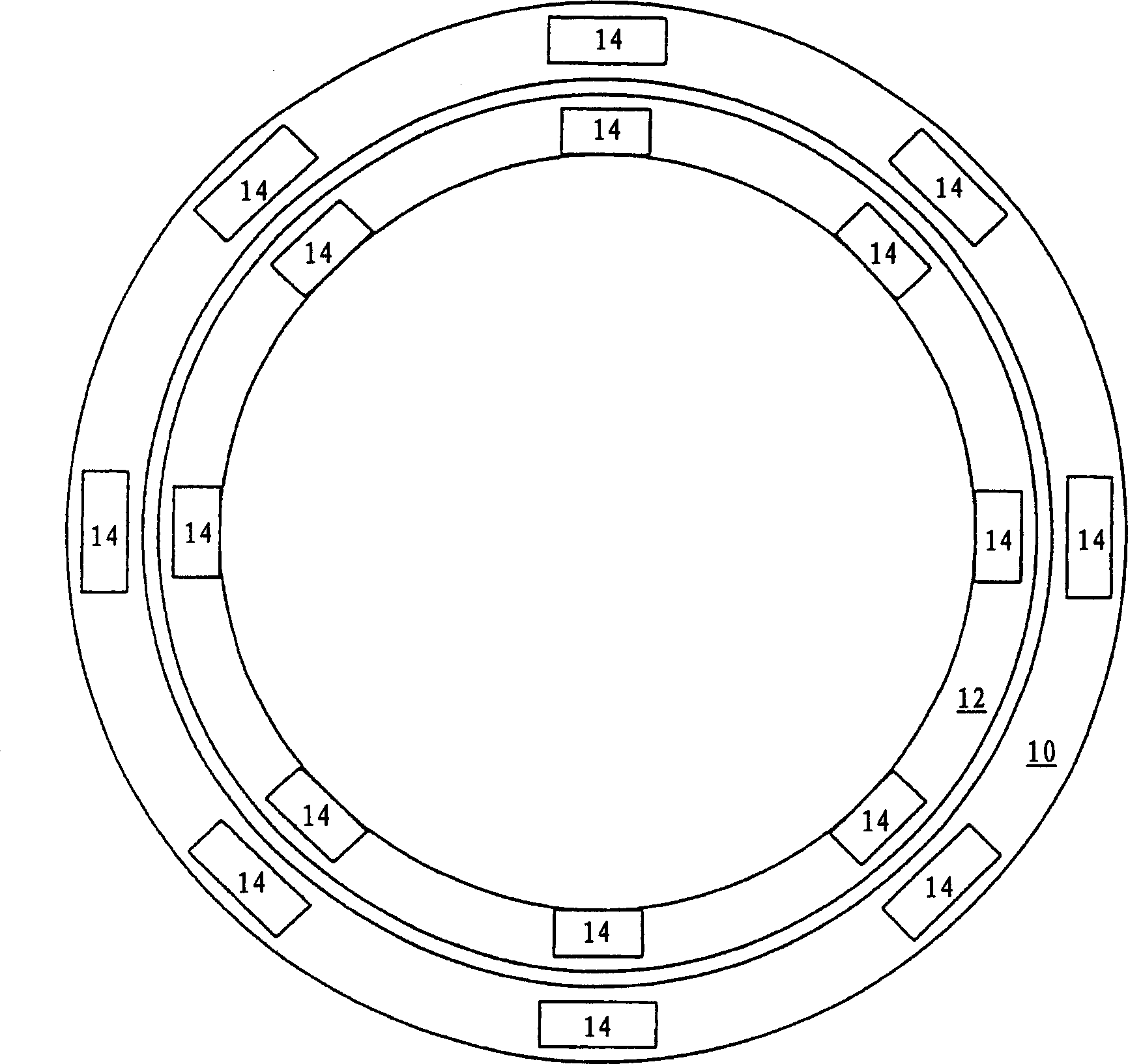
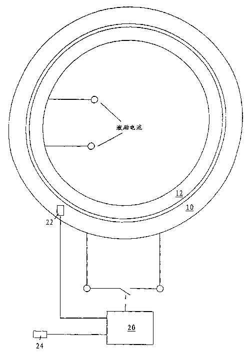
[0018] figure 1 is a more simplified view showing a generator comprising a stator 10 and a rotor 12 . The stator 10 has connection terminals at which electrical energy can be taken off during normal operation. The rotor 12 also has connection terminals by means of which an excitation current is supplied.

[0019] Shown between the connection terminals of the stator 10 are contacts that are actuated by the control device 20 and short-circuit the stator connections.

[0020] The control device 20 detects the temperature of the generator (in this case the stator) and the temperature of the surroundings of the wind energy installation by means of two temperature sensors 22 , 24 .

[0021] If the temperature of the stator detected by the sensor 22 is lower than the ambient temperature detected by the sensor 24, the contacts between the connection terminals of the stator are closed, thereby forming a short circuit.

[0022] Next, a predetermined excitation current is fed into the...


PUM


Abstract

A method for operating a wind energy plant in which the ambient air around the generator and the temperature of the generator itself are determined using temperature sensors (22,24). The temperature difference is determined and if necessary the generator is heated so that its temperature is equal to or greater than the surrounding air temperature. An independent claim is made for an operating method in which the humidity precipitation is measured on the generator or other electrically sensitive plant components and the generator heated if the humidity precipitation lies above a pre- determined level.

Description

technical field [0001] The invention relates to a method of controlling a wind power installation and, in particular, to a wind power installation for carrying out the method. Background technique [0002] Wind energy installations have long been known and have recently been increasingly used as environmentally friendly energy generators. [0003] Wind energy installations are logically exposed to the influence of the weather. A problem which has a great impact on wind energy installations is moisture, and wind energy installations with electrical systems must be protected to a greater extent against moisture. [0004] However, such devices cannot be hermetically closed to reliably prevent the ingress of moisture, so moisture must be kept away from certain parts of the device by additional encapsulating means such as housings. However, such an encapsulation is not feasible, especially in the region of wind energy plant pods with relatively large metallic masses such as gen...

Claims


Application Information

Patent Timeline
IPC IPC(8): F03D7/00F03D9/25F03D80/00H02P9/00
CPCF03D9/002F03D11/00Y02E10/723H02P29/005Y02E10/725Y02E10/722H02P9/02H02P2101/15F03D80/00H02P29/62F03D9/25F03D80/60H02J2300/28H02J3/381Y02E10/72Y02E10/76
Inventor 阿洛伊斯·沃本
Owner 阿洛伊斯沃本
Learn More