
Cooking vessel grip and relative manufacturing method

A technology for cooking containers and handles, which can be applied to the support of cooking appliances, cooking utensils, manufacturing tools, etc., and can solve the problems of increasing the risk of burns for users, slow cooling, and low thermal conductivity

Active Publication Date: 2004-09-01
LA TERMOPLASTIOC F B M SRL
View PDF0 Cites 0 Cited by
  • Summary
  • Abstract
  • Description
  • Claims
  • Application Information

AI Technical Summary

Problems solved by technology

However, due to the thickness and low thermal conductivity of the molded plastic material, solid handles cool very slowly, increasing the risk of burns to the user

Method used

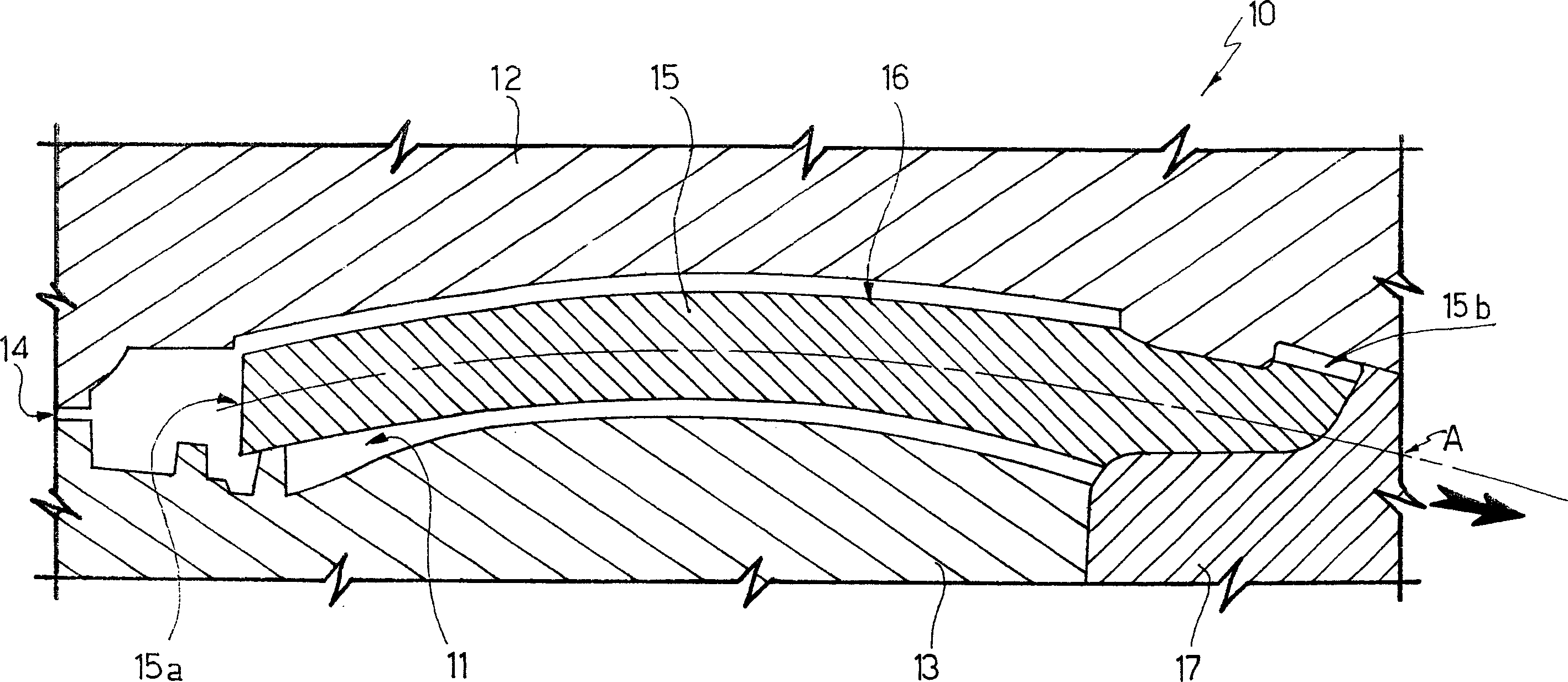

Image

  • Cooking vessel grip and relative manufacturing method
  • Cooking vessel grip and relative manufacturing method
  • Cooking vessel grip and relative manufacturing method

Examples


Embodiment Construction

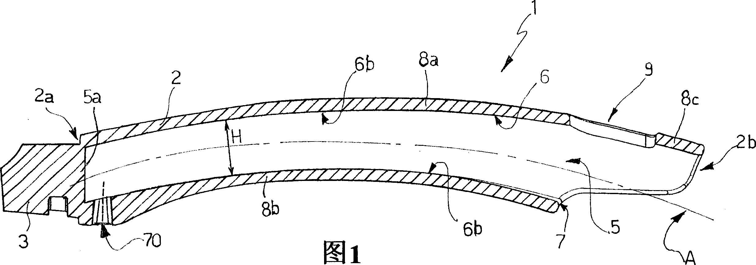
[0020] Referring to Figures 1 and 2, a cooking vessel handle, in particular a frying pan handle is generally indicated as 1 and comprises an elongated, integral body 2 molded from plastics material. The body 2 is preferably made of a thermosetting polymer material, especially a phenol-formaldehyde molding resin such as Bakelite.

[0021] The main body 2 is a hollow tubular body closed at one end, extending longitudinally along the axis A and having a longitudinal curved profile. Specifically, the axis A is the central axis of symmetric bending of the main body 2 .

[0022] The first end 2a of the body 2 has means 3 of any known type for connection to a cooking vessel, which may be a known frying pan or steamer, not shown for simplicity. Specifically, a connection portion 3 protruding from the first end 2a of the main body 2 is used to connect with the cooking container in a known manner; and the connection with the cooking container can be fixed or reversible .

[0023] The...


PUM


Abstract

A cooking vessel grip has an elongated, one-piece body (2) made of plastic material and having, at a first end (2a), a connecting portion (3) for connection to a cooking vessel; and the body (2) has, internally, a longitudinal cavity (5) extending at least along a portion gripped in use.

Description

technical field [0001] The invention relates to a cooking container handle, in particular to a frying pan handle and a corresponding manufacturing method thereof. Background technique [0002] Known food cooking containers such as frying pans or steamers usually have a handle by which the user can directly pick up the pan even while cooking or when the container is still hot to some extent. And to enhance insulation, most handles are made of a (polymer) plastic material, usually a heat-curing resin such as Bakelite rather than metal. [0003] In the case of a frying pan (that is, a generally round, low-sided, outwardly curved cooking vessel with a handle), most common handles include a generally elongated body with a One end has a connector for attaching to a frying pan. The body is typically integrally molded from a thermoset polymer material and is substantially solid except for a small seat for receiving a decorative insert or fastening means, such as screws or rivets, ...

Claims


Application Information

Patent Timeline
Patent Type & Authority Applications(China)
IPC IPC(8): A47J36/00A47J36/34A47J45/06A47J45/07B29C45/26
CPCA47J45/071A47J45/061B29C45/2614B29C45/261A47J36/34
Inventor 马尔科·穆纳里
Owner LA TERMOPLASTIOC F B M SRL
Learn More