
Inductive components, laminated electronic components, laminated electronic components modulars and method for mfg. these components and modulars

A technology of inductive components and electronic components, which is applied in multilayer circuit manufacturing, inductor/transformer/magnet manufacturing, electrical components, etc., and can solve problems such as difficulty in obtaining laminated electronic components at low cost

Inactive Publication Date: 2004-08-11
TDK CORPARATION
View PDF4 Cites 19 Cited by
  • Summary
  • Abstract
  • Description
  • Claims
  • Application Information

AI Technical Summary

Problems solved by technology

Therefore, it is difficult to obtain laminated electronic components cheaply

Method used


Image

  • Inductive components, laminated electronic components, laminated electronic components modulars and method for mfg. these components and modulars
  • Inductive components, laminated electronic components, laminated electronic components modulars and method for mfg. these components and modulars
  • Inductive components, laminated electronic components, laminated electronic components modulars and method for mfg. these components and modulars

Examples


Embodiment Construction

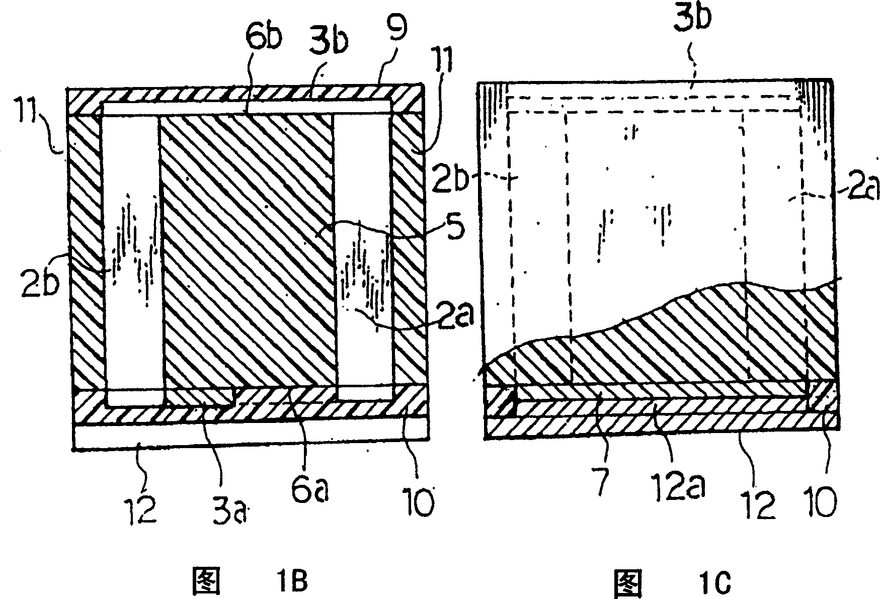
[0086] FIG. 1A shows an embodiment of an inductive element according to the invention in a perspective view. FIG. 1B shows the structure of a coil in the inductor coil in a cross-sectional view. FIG. 1C shows the structure of an electrode in the inductor element in a cross-sectional view. FIG. 2A shows the inductance element in a bottom view. Figure 2B The inductance element is shown in a cross-sectional view.

[0087] In FIGS. 1A-1C and FIGS. 2A and 2B, reference numeral 1 denotes a rectangular spiral coil. The coil 1 includes a pair of parallel conductive members 2a and 2b and a pair of bridging conductive members 3a and 3b. Each pair of parallel conducting members 2a and 2b forms two of the four sides of a turn of the coil 1 . Each pair of bridging conductors 3a and 3b forms the other two sides of a turn of the coil 1 . The rectangular spiral coil is formed by connecting adjacent parallel conductive members 2a and 2b to each other by bridging conductive members 3a and ...


PUM

PropertyMeasurementUnit
thicknessaaaaaaaaaa
thicknessaaaaaaaaaa

Abstract

A laminated electronic component including at least one inductance element and produced froma laminate having electrical insulators and electrical conductors laminated alternately. The inductance element is formed as a helical coil having a plurality of turns each constituted by four sides. The inductance element has pairs of parallel conductor pieces and pairs of bridging conductor pieces. Each pair of parallel conductor pieces form two of the four sides of one turn of the coil. Each pair of bridging conductor pieces form the other two sides of one turn of the coil. Grooves are formed in the laminate to thereby form the parallel conductor pieces. The grooves are filled with an electrically insulating material. The bridging conductor pieces are formed on the electrically insulating material.

Description

technical field [0001] The present invention relates to inductive components, laminated electronic components having at least built-in inductive and capacitive elements, laminated electronic component modules having at least one built-in inductive element among the inductive and capacitive elements, and methods of manufacturing these components and modules . Background technique [0002] For example, Patent Document 1 discloses a ceramic electronic component having a laminated inductor and a laminated capacitor integrally stacked by printing as one laminated electronic component with built-in inductor and capacitor elements. [0003] For example, Patent Document 2 discloses a ceramic electronic component having a multilayer inductor and a multilayer capacitor integrally stacked by a multilayer method. [0004] For example, Patent Document 3 discloses an electronic component having a multilayer spiral coil formed on a semiconductor chip. [0005] For example, Patent Documen...

Claims


Application Information

Patent Timeline
Patent Type & Authority Applications(China)
IPC IPC(8): H01F17/00H01F17/02H01F27/00H01F41/04H05K1/16H05K3/46
CPCH01L2924/0002H05K2201/097H05K1/165H01F41/041H01L2224/48091H01L2224/48227H01L2924/19105H01F17/0033H05K3/4602H01L2924/00014B62M3/08
Inventor 高谷稔远藤敏一
Owner TDK CORPARATION
Learn More