
Method for producing spiral diaphragm pieces

A spiral and diaphragm technology, applied in the field of spiral diaphragm parts, can solve problems such as breakage, poor wrinkle accuracy, wrinkling, etc., to reduce the degree of heating and compression, ease heating/compression conditions, The effect of low bending resistance

Inactive Publication Date: 2004-07-07
NITTO DENKO CORP
View PDF3 Cites 13 Cited by
  • Summary
  • Abstract
  • Description
  • Claims
  • Application Information

AI Technical Summary

Problems solved by technology

[0007] However, the method of forming only one line or one dotted line has the disadvantage that wrinkles cannot be formed sufficiently, and this tends to be twisted in a subsequent winding step, etc., resulting in "wrinkling" or "breakage"
The method of heating only has the disadvantage that the straightness or perpendicularity of the wrinkles is poor

Method used


Image

  • Method for producing spiral diaphragm pieces
  • Method for producing spiral diaphragm pieces
  • Method for producing spiral diaphragm pieces

Examples


example 1

[0080] A 924 mm wide film (NTR-759HR) manufactured by Nitto Denko Co., Ltd. was unwrapped while continuously heat-sealing 5 mm over a width of 10 mm from each side edge. A fusion-bonded tape having a width of 20 mm was applied to the edge of the permeation side of each fusion-bonded portion under a pressure of 0.05 MPa while avoiding wrinkling. Make sure there are no wrinkles. A PET tape No. 31B (manufactured by Nitto Denko Corporation) having a width of 50 mm was attached to the feeding side of the film at the same interval of 750 mm in the length direction while avoiding wrinkling. After applying the tape, a line was formed with a pressure of 200 N on each part where the corrugation was to be formed, using a metal sharp tool with a width of 0.5 mm and a die as a receiving tool. A feed-side channel material made of PP with a width of 924 mm was cut to 750 mm in advance. Alternately fix the cut feed side channel material on the position where the PET tape has been pasted. T...


PUM


Abstract

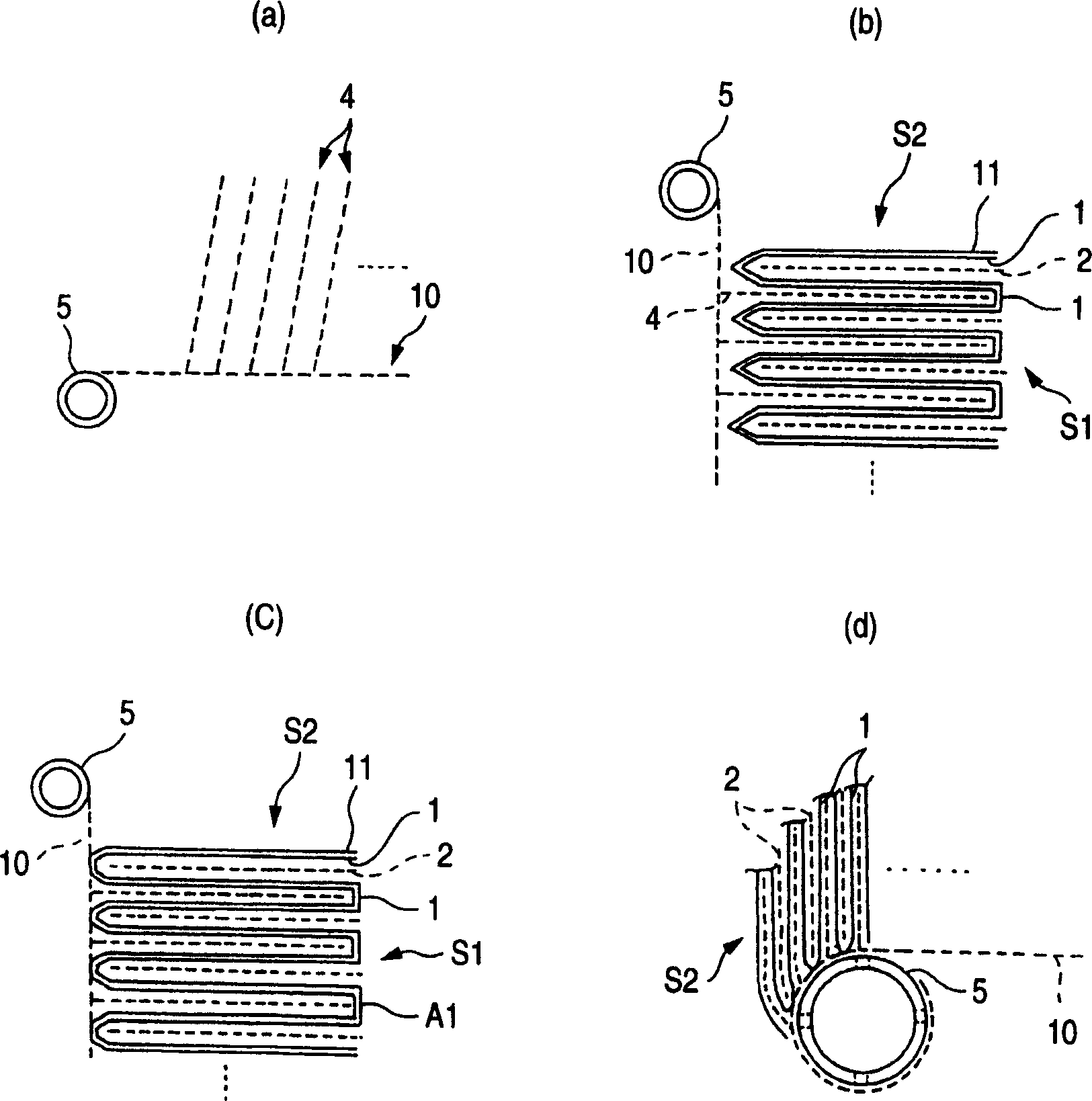
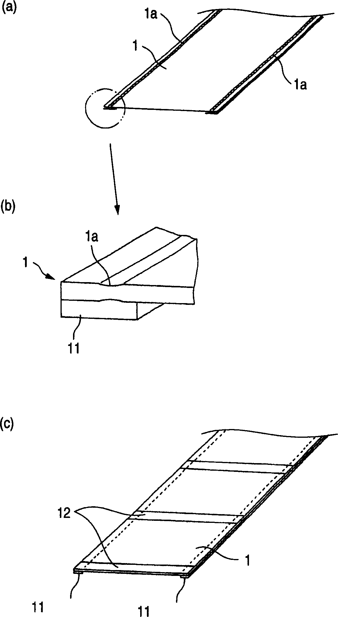
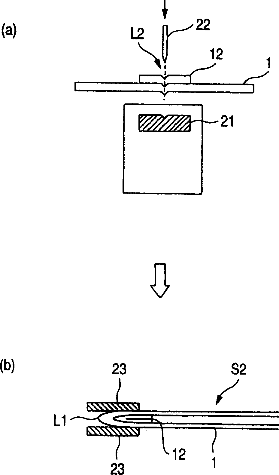
A process for spiral membrane element production is disclosed in which creases are stably and sufficiently formed to thereby enable the later step of winding or the like to be smoothly conducted while eliminating the 'wrinkling' or 'breakage' caused by the distortion of creased parts. The process comprises the step of forming a multilayer structure S2 comprising a membrane 1 which has been folded, a feed-side passage material disposed on the feed side of the folded membrane 1, and a permeation-side passage material disposed on the permeation side of the folded membrane 1 and the step of spirally winding at least the multilayer structure S2 on a perforated core tube 5, wherein the folded membrane 1 is obtained by forming beforehand in a membrane a folding initiation part L2 reduced in bending resistance along each of folding lines L1 for the membrane, folding the membrane 1 at the folding initiation parts L2, and heating and pressing the membrane 1 during and / or after the folding.

Description

technical field [0001] The present invention relates to a method of producing a helical membrane member for separating a specific component from various fluids (liquid or gas). More particularly, the present invention relates to an improved method of corrugating a membrane for use in a helical membrane member. Background technique [0002] The structure of the conventional spiral membrane piece is known to be obtained by placing the permeate side channel material on the permeate side of the two membrane pieces; sealing the three sides of the membrane pieces to form a pouch-shaped layered product ; connecting a set of such layered products (membrane blades) with a perforated core tube; and helically winding the connected layered products with feed side channel material placed between the layered products. Additionally, there are membrane elements that use two or more sets of this layered product (membrane vanes) to reduce the passage length on the permeate side. [0003] Th...

Claims


Application Information

Patent Timeline
Patent Type & Authority Applications(China)
IPC IPC(8): B01D63/10B01D63/00B01D67/00B01D69/00
CPCB01D63/10
Inventor 入江薰稻垣智弘小栗栖达也
Owner NITTO DENKO CORP
Learn More