Single-slot cable clamp

A technology of single-slot line clamps and clamping blocks, which is applied in the direction of pipe supports, electrical components, pipes/pipe joints/pipe fittings, etc., and can solve problems such as energy loss and waste

Inactive Publication Date: 2004-06-30
上海恒鼎电力器材有限公司
View PDF0 Cites 4 Cited by
  • Summary
  • Abstract
  • Description
  • Claims
  • Application Information

AI Technical Summary

Problems solved by technology

[0002] my country's electric power fittings are mainly made of malleable cast iron. Due to the structure of a closed magnetic circuit to form hysteresis and eddy current, resulting in energy loss and huge waste

Method used


Image

  • Single-slot cable clamp
  • Single-slot cable clamp

Examples


Embodiment Construction

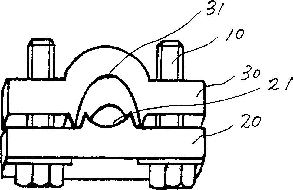
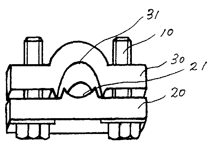
[0006] In the figure, a single-groove wire clamp is mainly composed of a compression bolt 10 and a lower clamping block 20. The compression bolt 10 penetrates into the screw hole of the lower clamping block 20, and the lower clamping block is provided with a raised U-shaped The clamping groove 21 is also screwed with a block-shaped upper clamping block 30 that is provided with a U-shaped clamping groove 31 matching the lower clamping block 20 on the compression bolt 10 . Among them, the upper and lower clamping blocks are made of high-strength copper. When in use, it is only necessary to tighten the bolts so that the upper clamping block matches the lower clamping block and clamps the wire.


PUM


Abstract

The clamp comprises of pressure bolt and lower fixture block. The pressure bolt passes through bolthole on the lower fixture block. Raised U typed clamping groove is set at the lower fixture block. A lumpy is revolved into the pressure bolt, and upper fixture block of U typed clamping groove is set at the pressure bolt to match the lower fixture block. The said upper and lower fixture block are made from copper. The invention provides features of reasonable structure and smart design. Surface contact between the upper fixture block and conducting wire makes proper fastening so as to overcome disadvantages of reduced holding power caused by creep of wires in traditional clamp. The invention lowers dissipation of energy, improving circuit equipment towards target of 'long service life, zero defects and exemption from inspection'.

Description

Technical field: [0001] The invention relates to electric equipment, in particular to a wire clamp suitable for distribution lines. Background technique: [0002] my country's electric power fittings are mainly made of malleable cast iron. Due to the structure of a closed magnetic circuit to form hysteresis and eddy currents, resulting in energy loss and huge waste. Invention content: [0003] The technical problem to be solved by the present invention is to provide a copper single-slot wire clip that can effectively overcome the above-mentioned defects, save energy and make surface contact with the wire. The technical solution adopted by the present invention to solve the technical problem is that a single-slot wire clamp is mainly composed of a pressing bolt and a lower clamping block, and the pressing bolt penetrates into the screw hole of the lower clamping block. Its characteristics are: the lower A protruding U-shaped clamping groove is provided on the clamping bloc...

Claims


Application Information

Patent Timeline
Patent Type & Authority Applications(China)
IPC IPC(8): F16L3/10H02G3/30H02G3/32H02G7/00
Inventor 孙伟新
Owner 上海恒鼎电力器材有限公司
Why Eureka
Try Eureka