
High-energy static vanadium cell

A vanadium battery, high-energy technology, applied in the field of high energy storage static vanadium battery, can solve problems such as high price and restrictions

Inactive Publication Date: 2004-06-23
肖玉璋 +1
View PDF0 Cites 19 Cited by
  • Summary
  • Abstract
  • Description
  • Claims
  • Application Information

AI Technical Summary

Problems solved by technology

Although nickel-hydrogen batteries and lithium-ion batteries are gradually being used in mobile energy, they are also subject to certain restrictions due to other reasons such as high prices.

Method used


Image

  • High-energy static vanadium cell
  • High-energy static vanadium cell

Examples


Embodiment Construction

[0018] 1. Prepare 2.8 mol / liter tetravalent vanadium ion electrolyte (positive electrode electrolyte) and trivalent vanadium ion electrolyte (negative electrode electrolyte) first, put them into the positive and negative electrodes of high-energy static vanadium battery respectively, and then tartaric acid, The stabilizer composed of ethylene glycol and hydrazine hydrate is added to the positive and negative electrolytes according to the proportion of 2% of the total vanadium electrolyte, and then 0.5% activator is added to charge to reach 2.8 moles / liter of pentavalent vanadium ions And divalent vanadium ion electrolyte.

[0019] 2. First prepare 4.5 mol / liter tetravalent vanadium ion electrolyte (positive electrode electrolyte) and trivalent vanadium ion electrolyte (negative electrode electrolyte), put them into the positive and negative electrodes of the high-energy static vanadium battery respectively, and use carboxymethyl The stabilizer composed of cellulose, glycerol a...


PUM


Abstract

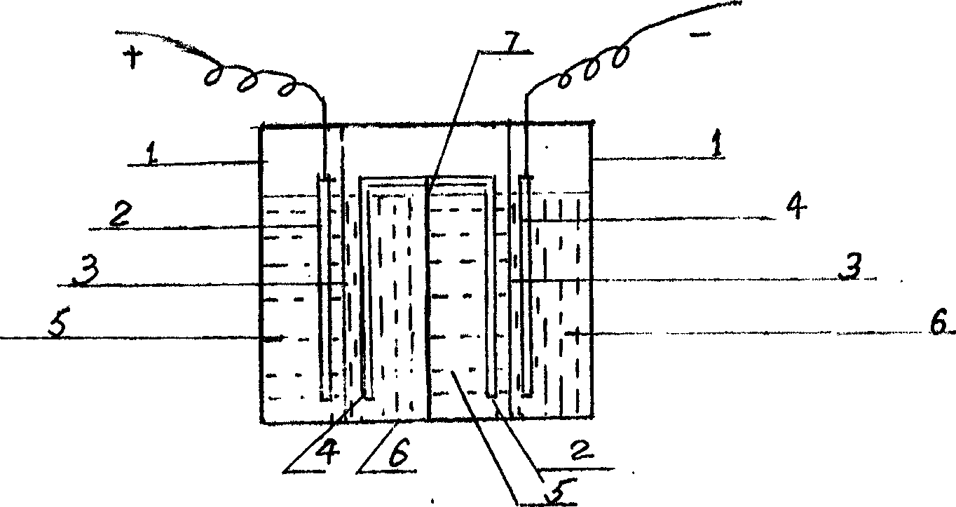
The high-energy static vanadium cell has its electrolyte set directly inside the electrode assembly and thus has no need outer electrolyte tank and electrolyte pump and is static. Its electrolyte contains high concentration vanadium ion stabilizer and activator. It has simple structure and may be rectangular or cylindrical. It has high specific energy, simple structure, light weight, fast charging, long service life and other advantages. It may be used in various vehicles, ships, electric tools, solar energy storage, etc.

Description

technical field [0001] The invention relates to an energy storage device. In particular, it relates to a high energy storage static vanadium battery. Compared with common liquid flow vanadium batteries, it has higher specific energy, and there is no need to set up positive and negative electrolyte tanks separately. Therefore, the volume is small and the structure is simple. Background technique [0002] The application of liquid flow vanadium batteries in large energy storage devices has been approved. A major feature of its design is that the electrolyte is stored in positive and negative electrolyte tanks, and then pumped into the electrode plate assembly. The reason why large-scale energy storage vanadium batteries are designed in this way is that the concentration of vanadium ions in the electrolyte has a certain limit. If the concentration exceeds a certain limit, pentavalent and divalent vanadium ions will precipitate or precipitate. Therefore...

Claims


Application Information

Patent Timeline
IPC IPC(8): H01G9/035H01M6/00H01M14/00
Inventor 肖玉璋肖侃
Owner 肖玉璋
Learn More