
Liquid crystal display and its driving method

A technology of a liquid crystal display device and a driving method, which is applied to static indicators, cathode ray tube indicators, optics, etc., and can solve problems such as increased costs of liquid crystal display devices

Inactive Publication Date: 2004-06-16
PANASONIC CORP
View PDF2 Cites 12 Cited by
  • Summary
  • Abstract
  • Description
  • Claims
  • Application Information

AI Technical Summary

Problems solved by technology

If this inappropriate situation is not reliably avoided, it is necessary to provide a memory such as a frame memory capable of storing more image signals than one line at the same time, which will lead to an increase in the cost of the liquid crystal display device.

Method used


Image

  • Liquid crystal display and its driving method
  • Liquid crystal display and its driving method
  • Liquid crystal display and its driving method

Examples


Embodiment Construction

[0057] Hereinafter, various embodiments of the present invention will be described with reference to the drawings.

[0058] (first embodiment)

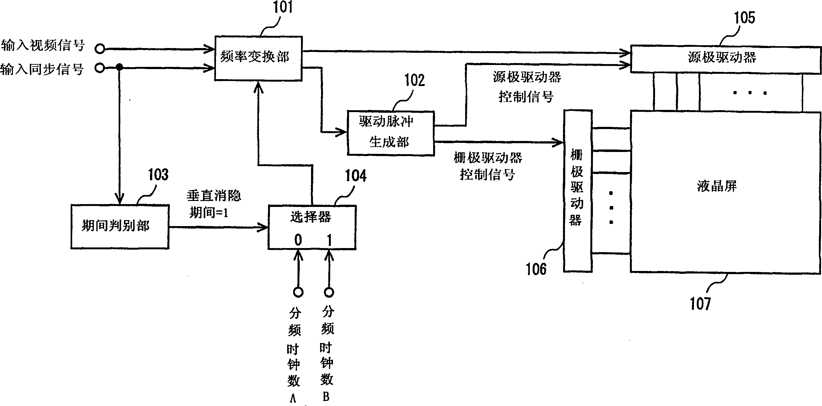
[0059] figure 1 shows the configuration of the liquid crystal display device according to the first embodiment of the present invention. figure 1 Among them, the liquid crystal display device includes a frequency conversion unit 101 , a drive pulse generation unit 102 , a period determination unit 103 , a selector 104 , a source driver 105 , a gate driver 106 , and a liquid crystal panel 107 . In this example, the liquid crystal panel 107 is of the OCB type.

[0060] An input video signal and an input synchronizing signal corresponding thereto (including a horizontal synchronizing signal and a vertical synchronizing signal) are supplied to the liquid crystal display device. The period discrimination unit 103 discriminates a vertical blanking period from the input synchronization signal. The selector 104 selects different numbers...


PUM


Abstract

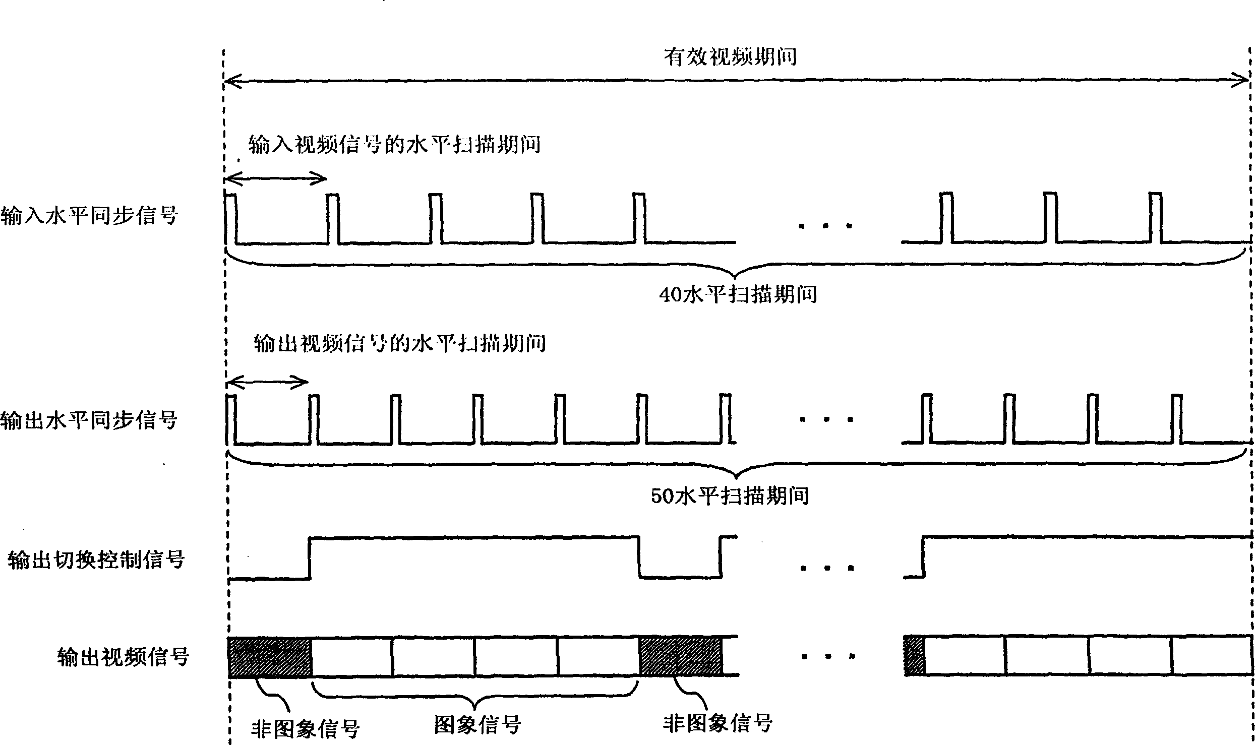
A frequency converting section (101), which is included in a liquid crystal display apparatus, generates an output video signal by inserting one non-image signal, which is to be concurrently written into pixels on L (L is an integer equal to or greater than two) gate lines of the liquid crystal panel, for one line, between image signals composing an input video signal, for corresponding L lines, and adjusting a number of horizontal scanning periods of the output video signal in a vertical blanking period so that a number of horizontal scanning periods composing one frame period is (L+1)x(2N+1) (N is an integer). Thus, when anti-back-transition driving is performed using a liquid crystal panel in OCB mode, it is possible to minimize increase in a driving frequency, prevent irregularity of brightness caused by AC driving of the liquid crystal panel, and reduce a cost.

Description

technical field [0001] The present invention relates to a liquid crystal display device, and particularly relates to a liquid crystal display device suitable for displaying moving images on a liquid crystal screen or using an optically self-compensated birefringence (OCB: Optically Self-Compensated Birefringence) liquid crystal screen. Background technique [0002] Liquid crystal display devices are often used as display devices such as computer devices, but it is also expected that their use in TVs will expand in the future. However, the Twisted Nematic (TN: Twisted Nematic) liquid crystal screen generally used at present has the disadvantages of narrow viewing angle and insufficient response speed. Therefore, when a TN-type liquid crystal panel is used for practical purposes, there are major problems that must be solved, such as a decrease in contrast due to parallax, blurred image outlines when displaying moving images, and the like. [0003] In recent years, studies on ...

Claims


Application Information

Patent Timeline
Patent Type & Authority Applications(China)
IPC IPC(8): G09G3/20G09G3/36G09G5/00
CPCG09G2320/0247G09G5/005G09G2300/0486G09G2310/061G09G5/006G09G5/008G09G2310/0205G09G2300/0491G09G2340/0421G09G2320/0261G09G3/3648G02F1/133
Inventor 有元克行太田义人小林隆宏村尾次男
Owner PANASONIC CORP
Learn More