Magnetron for microwave oven

A technology for magnetrons and microwave ovens, applied in the field of magnetrons, can solve problems such as inapplicability, increased output structure, and complexity

Inactive Publication Date: 2004-06-09
SAMSUNG ELECTRONICS CO LTD
View PDF0 Cites 8 Cited by
  • Summary
  • Abstract
  • Description
  • Claims
  • Application Information

AI Technical Summary

Problems solved by technology

However, this approach is not effective at attenuating harmonics across the bandwidth
Furthermore, in order to install an output structure for attenuating harmonics in the entire bandwidth, the output structure has to be enlarged, which becomes complicated
At this point, the above methods have certain limitations that cannot be applied

Method used


Image

  • Magnetron for microwave oven
  • Magnetron for microwave oven
  • Magnetron for microwave oven

Examples


Embodiment Construction

[0013] Reference will now be made in detail to embodiments of the present invention, examples of which are illustrated in the accompanying drawings, wherein like reference numerals refer to like parts throughout.

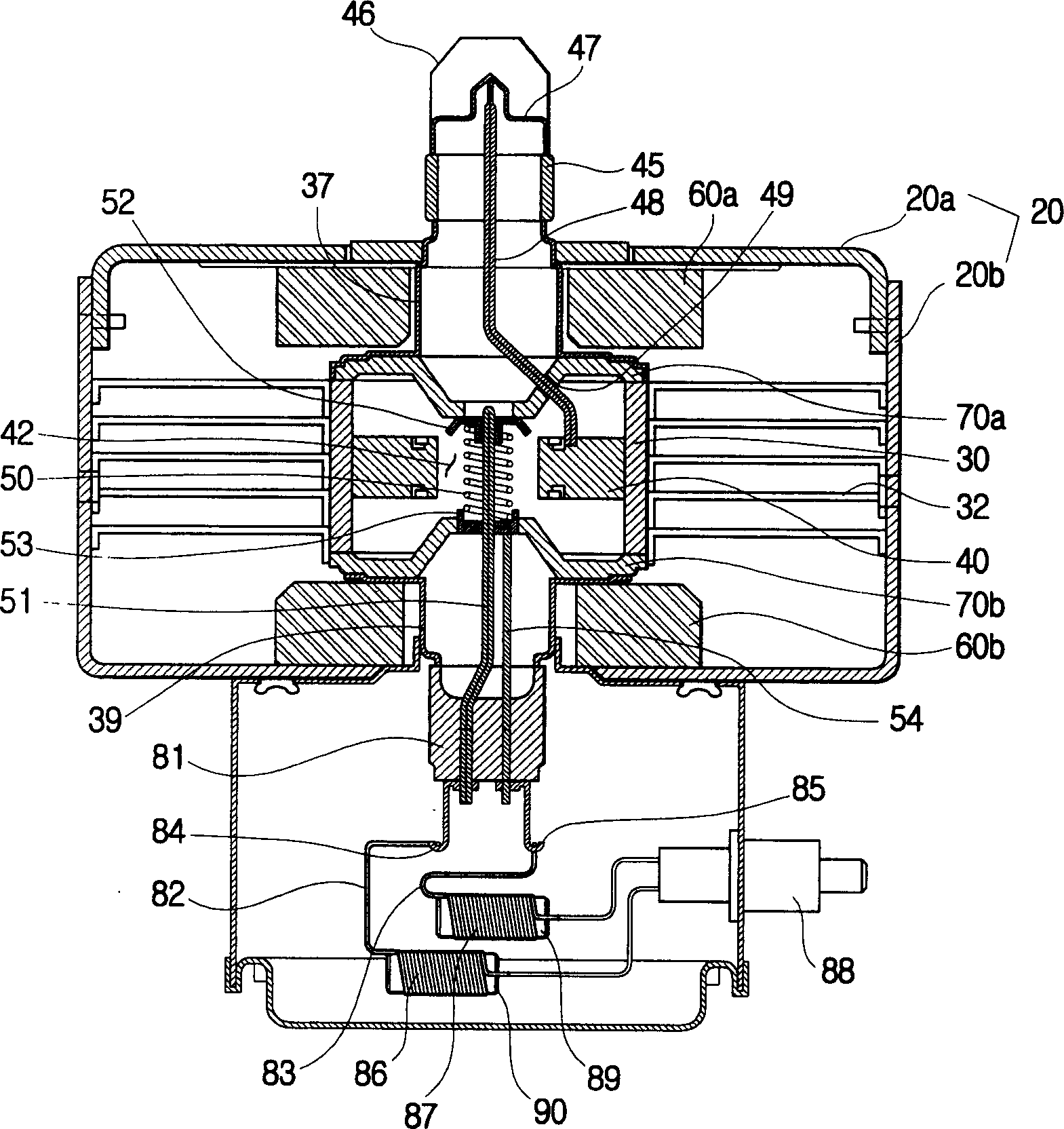
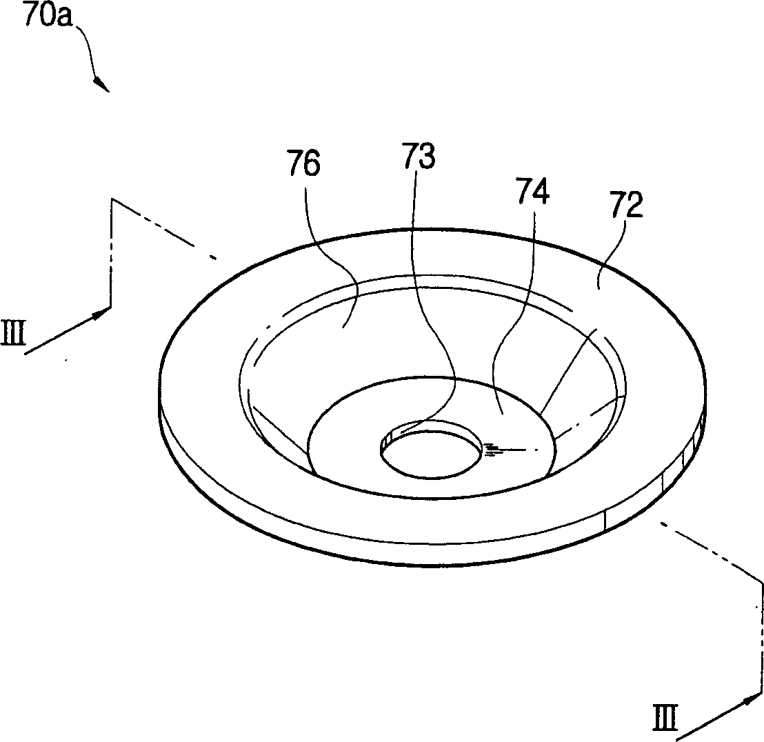
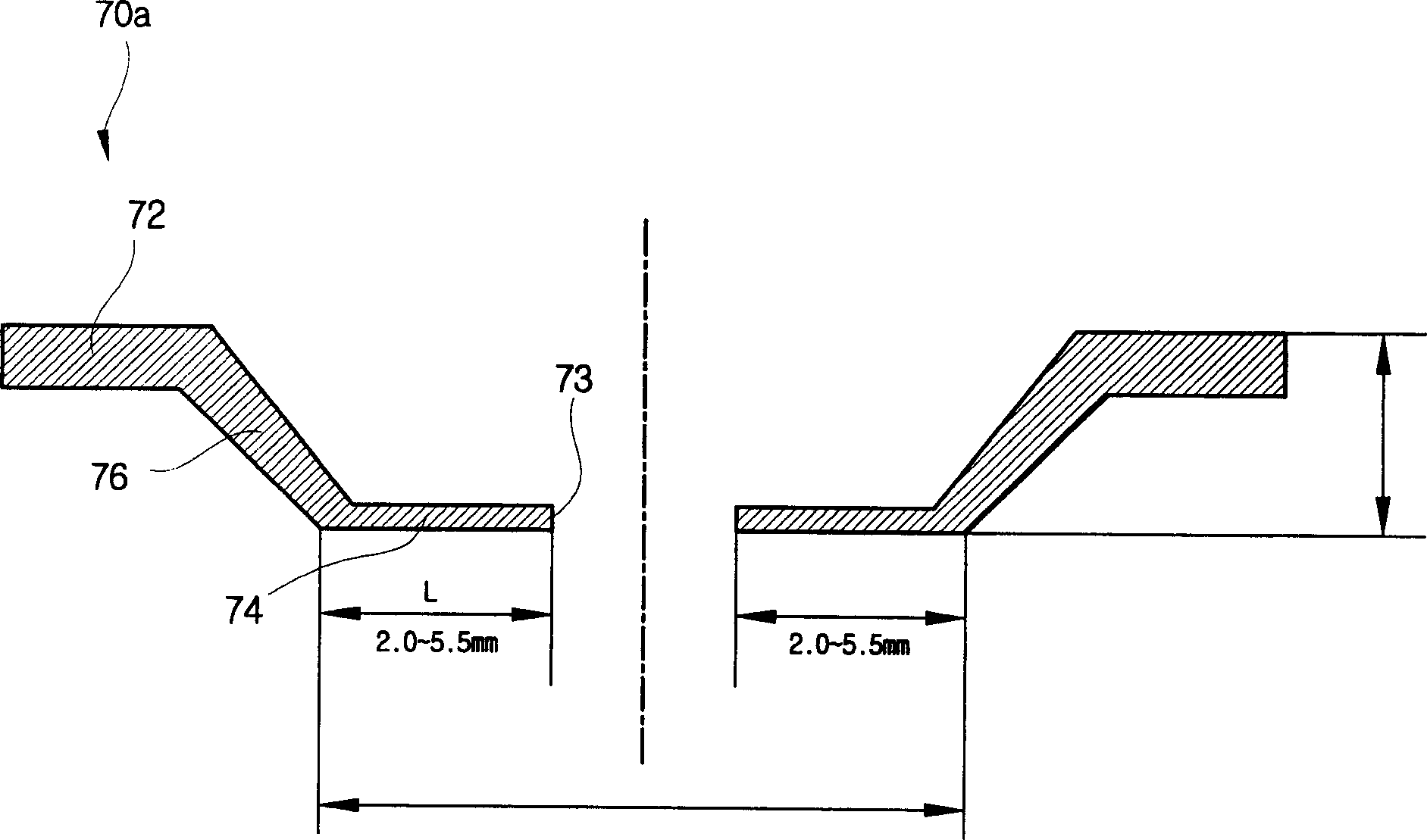
[0014] figure 1 Shown is a longitudinal sectional view of a magnetron for a microwave oven according to a preferred embodiment of the present invention. Such as figure 1 As shown, the magnetron used in microwave ovens includes: a yoke 20, an anode cylinder 30 installed inside the yoke 20, a plurality of burrs 40 installed inside the anode cylinder 30, and a filament 50 installed in the center of the burrs 40 , and an upper magnet 60a and a lower magnet 60b mounted on the upper and lower sides of the anode cylinder 30, respectively. The magnetron also includes an upper magnetic pole piece 70a and a lower magnetic pole piece 70b, which are installed between the anode cylinder 30 and the upper and lower magnets 60a, 60b, respectively, so that a central portion 74 can...


PUM


Abstract

A magnetron for a microwave oven includes a yoke, an anode cylindrical body installed inside the yoke, a plurality of veins mounted inside the anode cylindrical body, a filament installed in a center of the veins, and an upper magnet and a lower magnet respectively mounted on an upper side and a lower side of the anode cylindrical body. The magnetron also includes an upper pole piece and a lower pole piece respectively installed between the anode cylindrical body and the upper and lower magnets. A length (L) from an external tip of a central part of the upper pole piece to an internal tip thereof, on which a hollow part is formed, is adjusted to suppress harmonics in the magnetron. Thus, generation of the harmonics may be effectively attenuated, and an output of a microwave may be enhanced by preventing power consumption of the magnetron which may be large due to interrupting harmonics.

Description

technical field [0001] The invention relates to a magnetron used in a microwave oven, in particular to a magnetron used in a microwave oven, wherein the generation of harmonics can be weakened by changing the structure of the magnetic pole piece of the magnetron. Background technique [0002] A magnetron as a heating source in a microwave oven generates microwaves having a constant frequency (ie, a fundamental wave) through two poles of a magnet, and simultaneously generates harmonics having a frequency n times (where n is an integer) the fundamental frequency. As for the various components of harmonics, it has been found through scientific methods that even if the number of harmonics in a specific frequency band is small, it can cause obstacles to wireless communication and damage to the human body. Taking the above into consideration, the dose of harmonics can be legally limited. In addition, with the recent trend of satellite broadcasting, there is an increased need for ...

Claims


Application Information

Patent Timeline
Patent Type & Authority Applications(China)
IPC IPC(8): H01J23/10H01J23/15H01J23/54H01J25/50H01J25/587
CPCH01J23/54H01J23/10H01J25/587H01J23/15
Inventor 梁承哲
Owner SAMSUNG ELECTRONICS CO LTD
Why Eureka
Try Eureka