
Vacuum evaporator and method for manufacturing organic el display panel using the same

An evaporation and vacuum technology, which is applied in the fields of vacuum evaporation coating, lighting device, semiconductor/solid-state device manufacturing, etc. It can solve the problems of reduced quality of formed film and inability to uniformly evaporate.

Inactive Publication Date: 2004-06-02
NIPPON STEEL CHEMICAL CO LTD
View PDF1 Cites 59 Cited by
  • Summary
  • Abstract
  • Description
  • Claims
  • Application Information

AI Technical Summary

Problems solved by technology

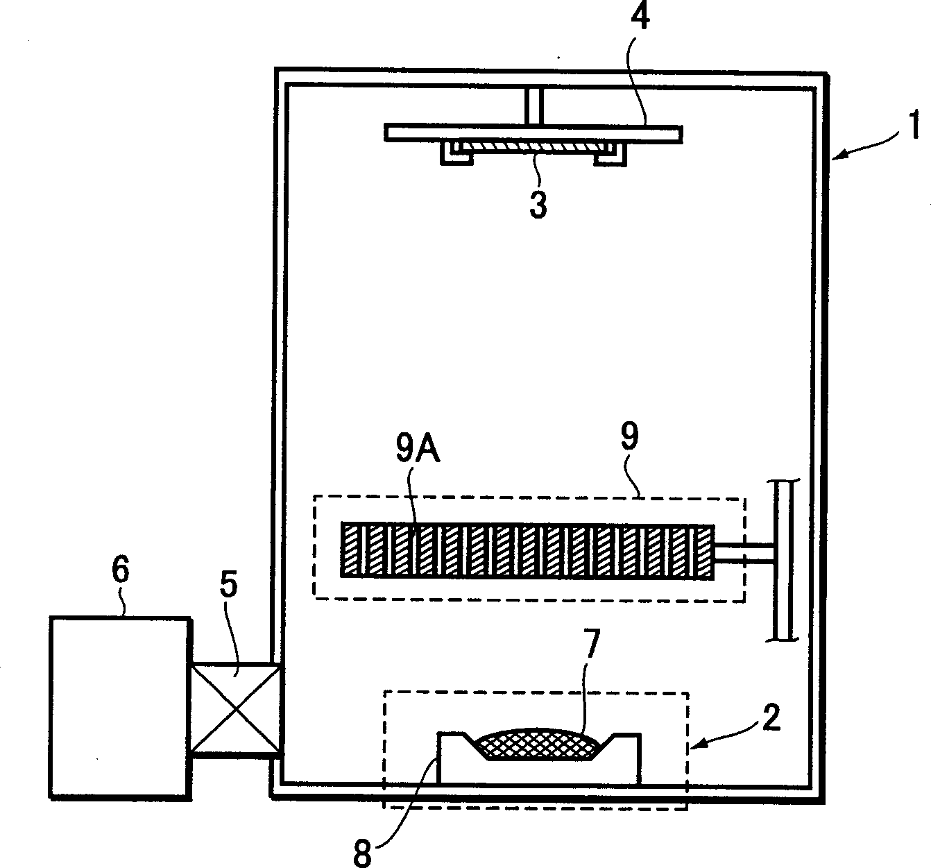
[0009] To sum up, in order to solve the problem that the quality of the existing vacuum evaporation device reduces the quality of the formed film and cannot be uniformly evaporated, the present invention provides a method that can improve the utilization rate of the evaporation material and improve the quality of the formed film, and A device capable of uniform vapor deposition on a large-area substrate

Method used


Image

  • Vacuum evaporator and method for manufacturing organic el display panel using the same
  • Vacuum evaporator and method for manufacturing organic el display panel using the same
  • Vacuum evaporator and method for manufacturing organic el display panel using the same

Examples


Embodiment Construction

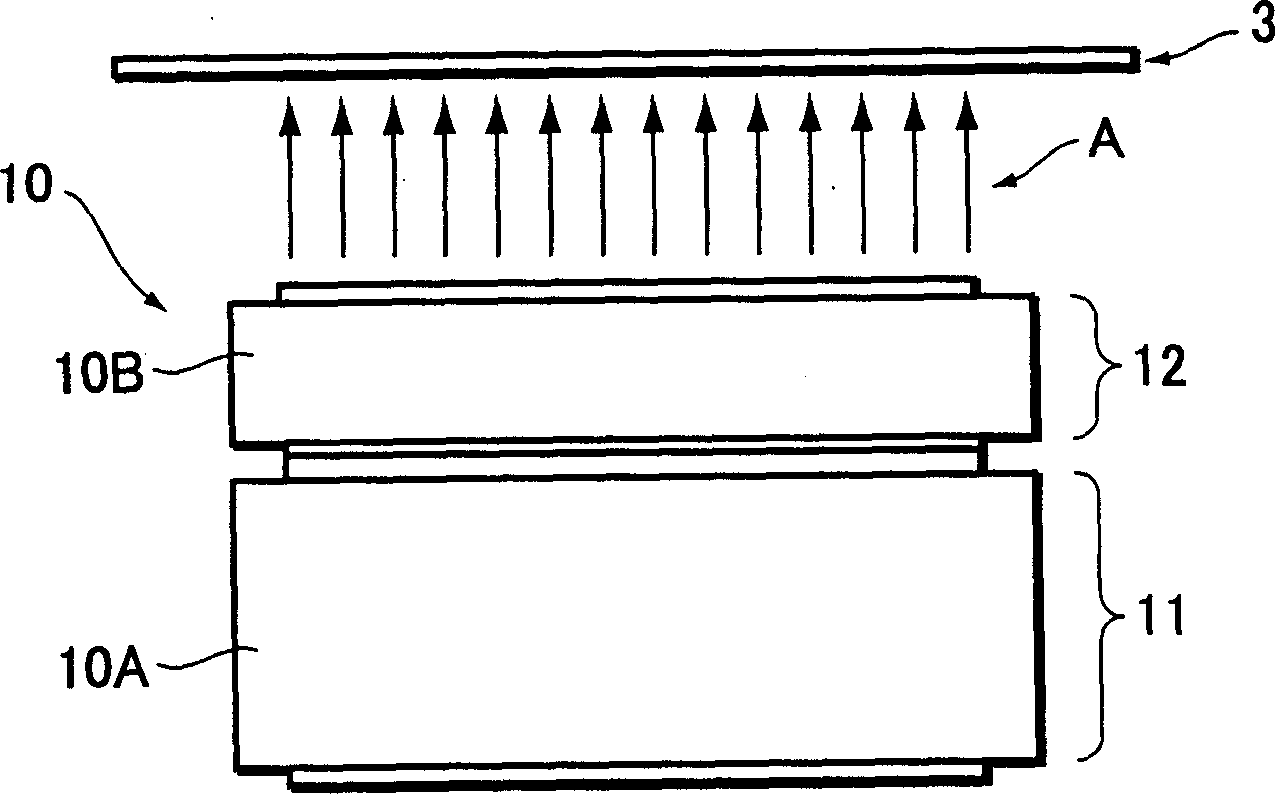
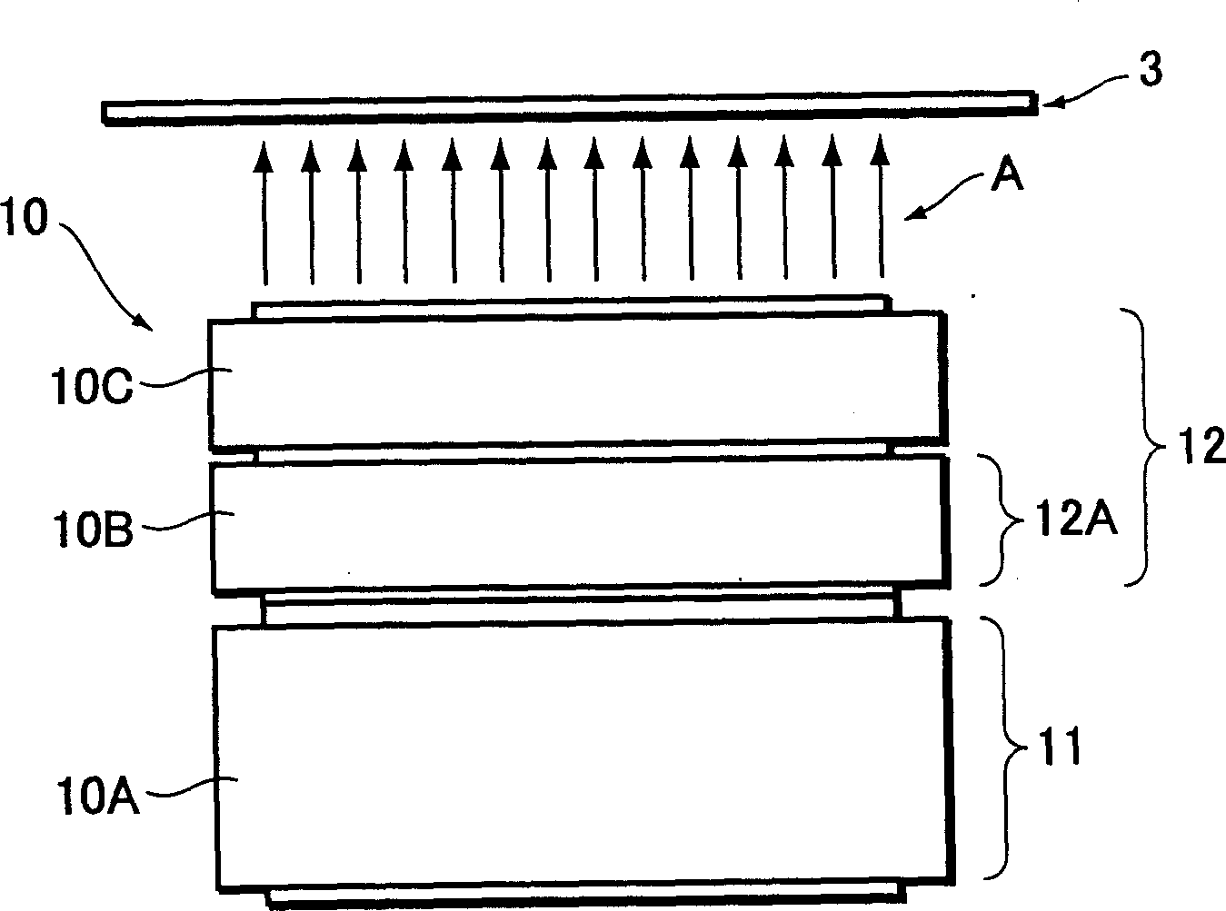
[0026] Such as figure 2 As shown, the evaporation source 10 is composed of laminated frames 10A and 10B, and the frame 10A at the lowest layer forms a heating part 11, and the heating part 11 contains an organic material and heats and evaporates the organic material, while the other layer The frame body 10B forms the vapor deposition flow control part 12, and controls the direction of the vapor deposition flow from the heating part 11 toward the vapor deposition object (substrate 3).

[0027] The direction of the vapor deposition flow of the organic material vaporized by the heating unit 11 is controlled by the vapor deposition flow control unit 12 , so that only the vapor deposition flow A passing there flows toward the substrate 3 . At this time, the organic material that has not passed through the vapor deposition flow control unit 12 does not escape from the stacked frames 10A, 10B, so it is all recovered in the frame 10A at the lowest level, and the organic material of t...


PUM


Abstract

There is provided a vacuum evaporator comprising an evaporation source (10) formed out of a stacked frame structure (10A, 10B), in which the bottom frame (10A) serves as a heating part (11) and another frame (10B) serves as an evaporation flow controller (12). This vacuum evaporator causes an improvement in utilization efficiency of a deposition material (B), an enhancement in qualities of a thin film and a uniform deposition on a larger-area substrate.

Description

technical field [0001] The invention relates to an evaporation device, in particular to a vacuum evaporation device and a method for manufacturing an organic EL display panel with the device. Background technique [0002] As a technique for forming a thin film on a substrate, there is conventionally known a vacuum evaporation method. In this vacuum evaporation method, a substrate is arranged on the opposite side of the evaporation source in a vacuum evaporation tank, and the evaporation flow generated by the heating evaporation source is irradiated on the surface of the substrate to form an evaporation on the substrate. Thin film of material. The vacuum vapor deposition apparatus for performing the vacuum vapor deposition basically includes a vacuum chamber, a vapor deposition source, a heating / evaporating device, a substrate holder, and the like. As the heating and evaporating device, an induction heating device, which uses a material that generates heat due to electromag...

Claims


Application Information

Patent Timeline
Patent Type & Authority Applications(China)
IPC IPC(8): H05B33/10C23C14/12C23C14/24H01L51/40H01L51/50H01L51/56
CPCC23C14/243C23C14/24
Inventor 泽田恭彦结城敏尚村山竜史尾越国三石井和男
Owner NIPPON STEEL CHEMICAL CO LTD
Learn More