Soft switching circuit without absorption loss
A soft switching, lossless technology, applied in the direction of electrical components, adjusting electrical variables, high-efficiency power electronic conversion, etc., can solve the problems of high production cost, decreased circuit work efficiency, complex circuit, etc., to improve work efficiency and power saving performance , the number of additional components is small, and the effect of simple circuit structure
- Summary
- Abstract
- Description
- Claims
- Application Information
AI Technical Summary
Problems solved by technology
Method used
Image


Examples
Embodiment 1
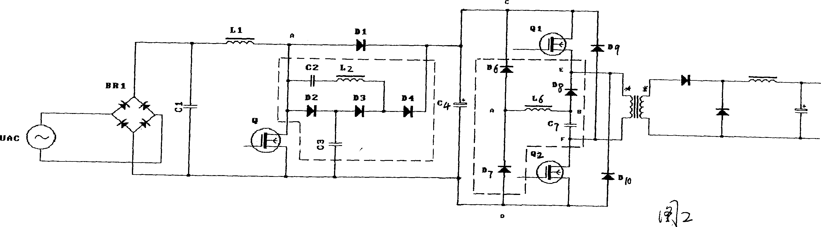
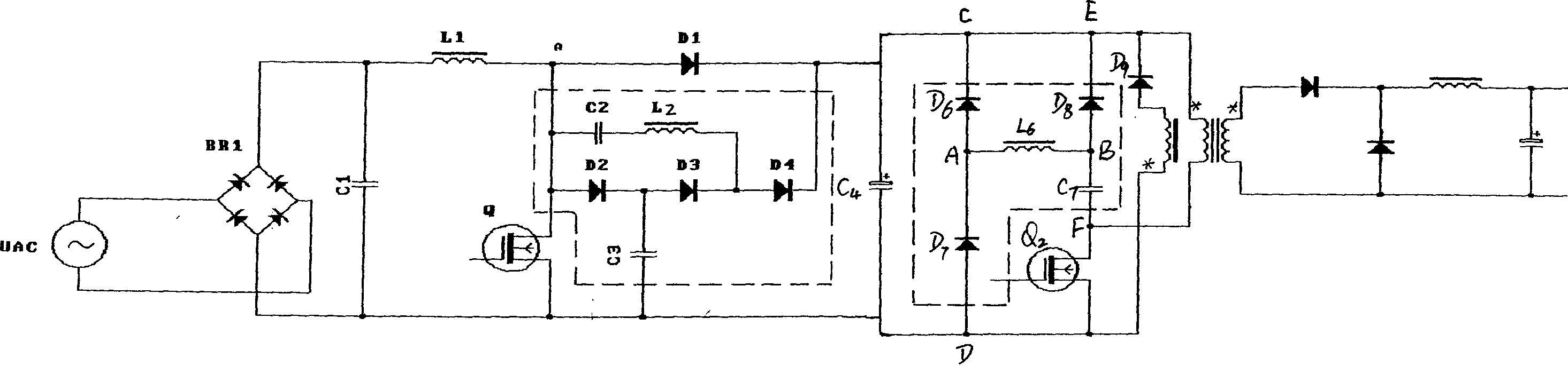
[0021] Embodiment 1: A soft switching circuit without loss absorption, used in BOOST booster circuit, the structure is that the alternating current passes through the bridge BR 1 rectified by the energy storage inductor L 1 Capacitance C 1 The composed circuit is then connected to the switch tube Q, and one end of the switch tube Q is used as the switch cathode, and the diode D 2 , Diode D 3 and diode D 4 A branch formed in series in the same direction, connected in parallel with the freewheeling diode D in the BOOST circuit 1 The two ends; and by the capacitance C 2 and inductance L 2 One end of the series resonant branch is connected to the diode D 1 The anode of the other end is connected to the diode D 3 with diode D 4 between; and between the diode D 2 with diode D 3 A capacitor C is connected between 3 One end of the capacitor C 3 The other end is connected to the cathode end of the switch tube. where the capacitor C 2 with inductance L 2 The resonant half...
Embodiment 2
[0024] Example 2: Diode D 6 and diode D 7 Connected in series in the same direction, diode D 6 The negative end of the diode is connected to the positive end of the input power supply, and the diode D 7 The positive terminal is connected to the negative terminal of the input power supply, and the diode D 6with diode D 7 There is an inductance L between 6 at one end, the inductance L 6 The other end of the diode is connected to D 8 positive electrode and capacitor C 7 One end of the capacitor C 7 The other end of the transformer is connected to the negative potential end when the primary coil of the transformer is excited, and is connected to the switch tube Q 2 The anode of the switch tube Q 2 The cathode is connected to the negative terminal of the input power supply, and then the diode D is forwardly connected in series. 10 Then connect to the positive potential terminal of the primary coil of the transformer when it is excited, the diode D 8 The negative pole of ...
Embodiment 3
[0026] Example 3: Diode D 6 and diode D 7 Connected in series in the same direction, diode D 6 The negative end of the diode is connected to the positive end of the input power supply, and the diode D 7 The positive terminal is connected to the negative terminal of the input power supply, and the diode D 6 with diode D 7 There is an inductance L between 6 at one end, the inductance L 6 The other end of the diode is connected to D 8 positive electrode and capacitor C 7 One end of the capacitor C 7 The other end of the transformer is connected to the negative potential end when the primary coil of the transformer is excited, and is connected to the switch tube Q 2 The anode of the switch tube Q 2 The cathode of the magnetic reset coil is connected to the negative terminal of the input power supply, the positive terminal of the magnetic reset coil (when the primary coil is excited) is connected to the negative terminal of the input power supply, and the negative terminal...
PUM
 Abstract
Description
Claims
Application Information
 - R&D
- Intellectual Property
- Life Sciences
- Materials
- Tech Scout
- Unparalleled Data Quality
- Higher Quality Content
- 60% Fewer Hallucinations
Browse by: Latest US Patents, China's latest patents, Technical Efficacy Thesaurus, Application Domain, Technology Topic, Popular Technical Reports.
© 2025 PatSnap. All rights reserved.Legal|Privacy policy|Modern Slavery Act Transparency Statement|Sitemap|About US| Contact US: help@patsnap.com