


Quick Research
Generate reliable direction feasibility study reports for your R&D in just a few steps.

Technical Q&A
Discover and master advanced knowledge NOW. Basics, ideas, possibilities, all at once.

Find Solutions
As an expert in R&D theories, this can generate solutions to your technical problems instantly.

Evaluate Feasibility
Analyze your overall solution with one click, know your potential R&D risks in advance.

Monitor Landscape
Get weekly tech updates, stay abreast of the latest tech innovations and key insights.
Head positioning controller, disk device cooperating same, and head positioning control method
A positioning control and controller technology, which is applied in the configuration/installation of recording heads, driving/moving recording heads, instruments, etc., and can solve problems such as non-tracking, deterioration of positioning accuracy, and resulting position errors.
- Summary
- Abstract
- Description
- Claims
- Application Information
AI Technical Summary
Problems solved by technology
Method used
Image

Examples
Embodiment approach 1
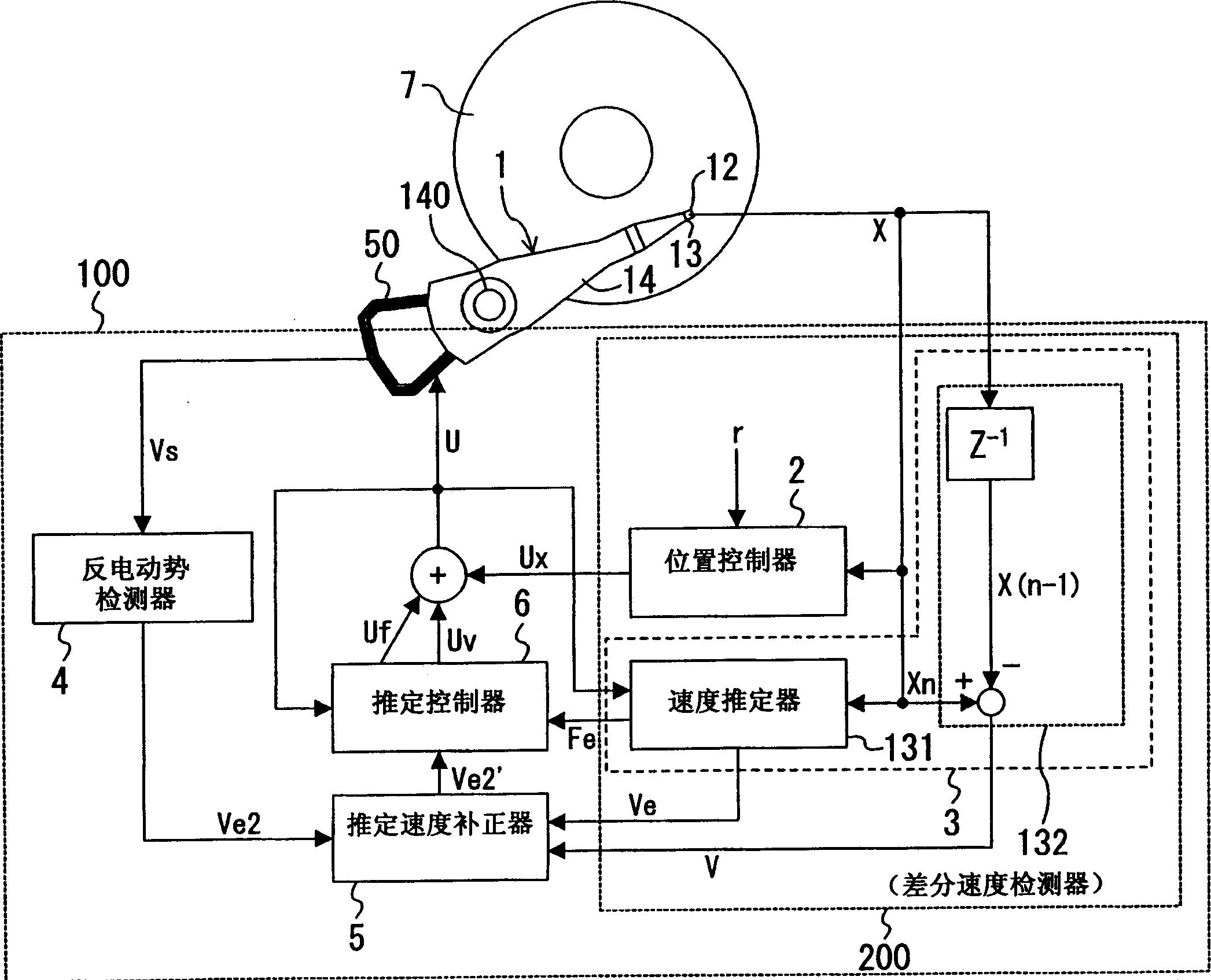
[0077] figure 1 is a block diagram showing the configuration of the head positioning control device according to Embodiment 1 of the present invention.
[0078] figure 1 Here, the center of a magnetic disk (hereinafter also simply referred to as a disk) 7 as a disk-shaped information recording medium is held as a rotation center, and the rotation is controlled by a rotation control mechanism such as a spindle motor, for example. A magnetic head (hereinafter referred to as head) 12 for recording and reproducing information on the disk 7 is integrally formed at the front end of the head slider 13 . The head slider 13 is mounted on the front end of the head support mechanism 14 . The head support mechanism 14 is driven by the actuator 50 around the rotation shaft 140 to perform the movement operation of the head 12 . The actuator 50 is provided with a voice coil motor (also referred to as a VCM) as a driving means, and the VCM moves the head 12 at the front end of the head s...
Embodiment approach 2
[0129] Figure 13 It is a block diagram showing the configuration of the head positioning control device according to Embodiment 2 of the present invention.
[0130] Figure 13 In the embodiment, the mechanism configuration of the control unit 102 is the same as that of the first embodiment, so the description thereof will be omitted here. In addition, to the same constituent elements as in Embodiment 1, the figure 1 and so on for the same sign.
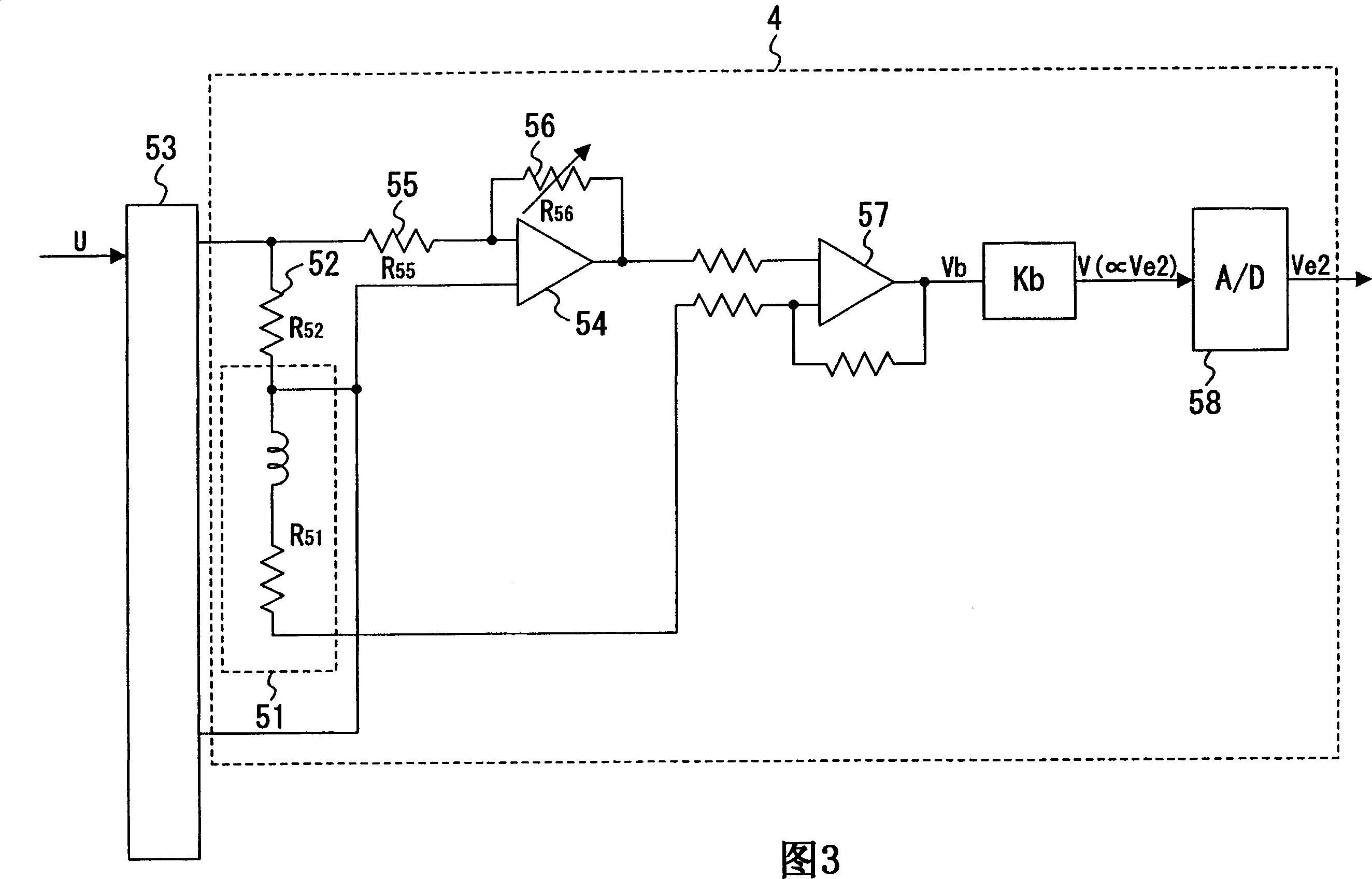
[0131] However, unlike the basic control unit 200 in Embodiment 1, the basic control unit 202 included in the control unit 102 does not need to have the speed detector 3 . The sensor head position signal x is input to the estimated speed corrector 5 as it is. In addition, the difference from Embodiment 1 is that the counter electromotive force detector 4 generates the estimated moving speed signal V based on a continuous (analog) signal from the actuator 50 constituted by a driving device such as a VCM. e2 , and the integrated ...
Embodiment approach 3
[0134] Figure 14 is a block diagram showing the configuration of the head positioning control device according to Embodiment 3 of the present invention.
[0135] Figure 14 In the present invention, the mechanism configuration of the control unit 103 is the same as that of Embodiments 1 and 2, so description thereof will be omitted here. In addition, to the same constituent elements as in Embodiment 1, the figure 1 and so on for the same sign.
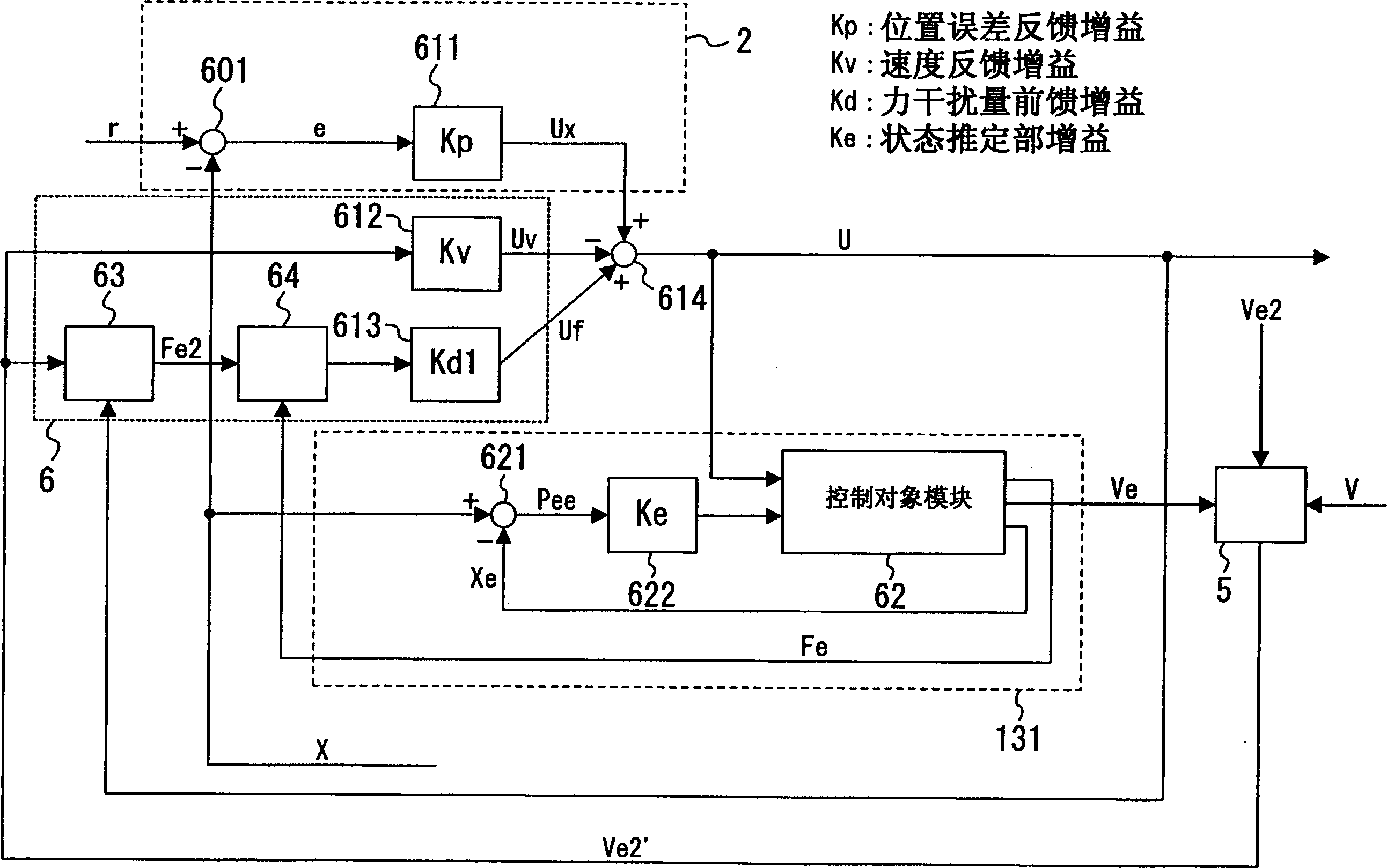
[0136] Unlike Embodiment 1, in the control unit 103, the estimation controller 6 only corrects the estimated speed signal V e2 ’ is set as the input signal, and the control value signal U is not input, and the estimated speed signal V is corrected. e2 ’ multiplied by the speed feedback gain K v , output speed control signal U v .
[0137] In addition, the position controller 2 equipped in the basic control unit 203 multiplies the position error signal e, which is the difference between the detection head position signal x and ...
PUM
 Abstract
Description
Claims
Application Information
 - R&D Engineer
- R&D Manager
- IP Professional
- Industry Leading Data Capabilities
- Powerful AI technology
- Patent DNA Extraction
Browse by: Latest US Patents, China's latest patents, Technical Efficacy Thesaurus, Application Domain, Technology Topic, Popular Technical Reports.
© 2024 PatSnap. All rights reserved.Legal|Privacy policy|Modern Slavery Act Transparency Statement|Sitemap|About US| Contact US: help@patsnap.com